This thread has been locked.

If you have a related question, please click the "Ask a related question" button in the top right corner. The newly created question will be automatically linked to this question.

eUART baud rate = 921600bps (for maximum bluetooth module) setting for MSP430FR5738

Other Parts Discussed in Thread: MSP430FR5738

As I wanted to use MSP430FR5738 for bluetooth sensor, I put 9600*3*32*16=14745600=14.7456MHz X'tal.

And try to set baud rate at 9600*3*32=921600=921.6kbps as follows,

UCA0CTL1 |= UCSWRST;
UCA0CTL1 = UCSSEL_2; // Set SMCLK as UCLk
UCA0BR0 = 1 ; // 1 = 921600 baud = 14745600/1/16
UCA0BR1 = 0;

// UCBRSx = 0x00 upper 8bit, UCBRFx = 0x0 4bit, UCOS16 = 0x1 4bit
UCA0MCTLW = 0x0001 ;

P2SEL1 |= BIT0 + BIT1; // pin selection for TXD and RXD
P2SEL0 &= ~BIT0;
P2SEL0 &= ~BIT1;

But, I got the baud rate of 311.5kbps. (1bit = 3.21uS )

Where do I go wrong?

Would you please show me the sample code to set the baud rate at 921.6kbps in C code please?

  • Hello Koyo,

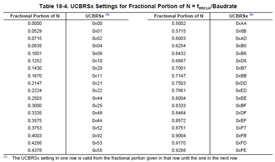
    I think problem is  UCBRSx and UCBRFx.

    .

    And ı think this is better


    UCA0CTL1 |= UCSSEL_2;

    UCA0CTL1 &=~UCSWRST;

  • Koyo Kegasa said:

    UCA0BR0 = 1 ; // 1 = 921600 baud = 14745600/1/16
    UCA0BR1 = 0;

    // UCBRSx = 0x00 upper 8bit, UCBRFx = 0x0 4bit, UCOS16 = 0x1 4bit
    UCA0MCTLW = 0x0001 ;

    Following the algorithm named "Baudrate settings quick set up" in chapter 18.3.10 Setting a Baud Rate, I would set: 2. UCOS16 = 0; UCA0BRW = 16u; 4. UCA0MCTLW = 0u; Regards, Peppe
  • Koyo Kegasa said:
    UCA0BR0 = 1 ; // 1 = 921600 baud = 14745600/1/16

    According to datasheet, maximum BITCLK is 5 MHz. You feed it 15MHz. It's possible that the 5MHz limit applies even if you add a further x16 divider by setting UCOS16 which divides the effective baudrate by 16.

    If this is true, there should be a note added to the datasheet.

    Try the following:

    use UCA0BR0 = 3 and test resulting baudrate. then use UCA0BR0=5 and test again.
    Now use UCA0BR0=16 and do NOT set UCOS16 bit.

    Please post the results.

  • I tried UCA0BR0 = 3 than the bit time is 3 times bigger = 9.6uS.

    As I prefer over sampling mode, I'll try other method later.

  • Koyo Kegasa said:
    I tried UCA0BR0 = 3 than the bit time is 3 times bigger = 9.6uS.

    Strange. It really looks like you don't have 15MHz on the clock. 9.6µs * 3 * 16 = 5MHz (exactly!).

    One thought that comes in mind: Maybe you have gotten an overtone crystal and it is running on baseband instead. beyond 10MHz, the likelyhood of getting an overtone crystal increases (below 10Mhz, all I*ve seen so far were baseband crystals)
    Overtone crystals have a base frequency that is usually 1/3 (or 1/5 etc.) of the nominal frequency. if load capacitance isn't properly matched, they might not oscillate on the nominal frequency but on baseband instead. This would explain the 1:3 error in the resulting baudrate.

    How to check: output SMCLK to a port pin and check the frequency. It likely is 14745600/3

    How to solve: well, get a baseband crystal or double-check your load capacitance. Use higher quality capacitors (with less tolerance). Measure the capacitance (well, that's maybe asking for too much. Most people don't have the equipment to reliably measure pF capacitances). And don't forget the pin an trace capacitances!

  • Oh! I never thought about it.

    Thank you very much!

    I also tried the low frequency mode ( not over sampling mode ) as below.

    UCA0BR0 = 16 ; // 1 = 921600 baud = 14745600/1/16
    UCA0BR1 = 0;

    UCA0MCTLW = 0x0000 ;
    UCA0CTL1 &= ~UCSWRST; // release from reset

    1bit = 3.2uS again!


    You are right Maybe X'tal OSC dosen't working properly?

    I'll check the clock sysutem today.

  • I checked the clock frequency. 

    //PJ.0/TDO/TB0OUTH/SMCLK/CD6

    PJSEL0 |= BIT0;
    PJSEL1 &= ~BIT0;
    PJDIR |= BIT0;

    I got 4.99MHz.

    You are right!

    I'll check the clock system!

    Thank you very much!

  • Now, it's X'tal OSC problem!

    I set the registers as follows.

    // Startup X'tal OSC clock system in 14.7456MHz.
    // XT1 setting 8~16MHz 2012-12-3 by Koyo Kegasa.
    PJSEL0 |= BIT5 + BIT4; // PJ.4 and PJ.5 are X'tal ports
    PJSEL1 &= ~BIT5;
    PJSEL1 &= ~BIT4;
    CSCTL0_H = 0xA5; // Unlock register
    CSCTL2 = SELM__XT1CLK + SELS__XT1CLK + SELA__XT1CLK; // set ACLK,MCLK,SCLK = XT1CLK
    CSCTL3 = DIVA_0 + DIVS_0 + DIVM_0; // set all dividers 1
    CSCTL4 = XTS + XT1DRIVE_1; // XT1 high frequency select + 8-16MHz drive select

    Using Oscilloscope

    MSP430FR5738IRGE
    pin21 = PJ.4/XIN = 14.8MHz 170mVrms 20mVaverage
    pin22 = PJ.5/XOUT = 14.8MHz 87mVrms 970mVaverage

    I can see the sine wave all right.

    But when I output SMCLK, 

    // output SMCLK on PJ.0 by Koyo Kegasa on 2012-12-7 10:30 AM
    PJSEL0 |= BIT0;
    PJSEL1 &= ~BIT0;
    PJDIR |= BIT0;

    and watch it using oscilloscope

    4.99MHz 1.877Vrms 1.786Vaverage is there.  

    What should I do next?

  • Koyo Kegasa said:
    Using Oscilloscope

    MSP430FR5738IRGE
    pin21 = PJ.4/XIN = 14.8MHz 170mVrms 20mVaverage
    pin22 = PJ.5/XOUT = 14.8MHz 87mVrms 970mVaverage

    I can see the sine wave all right.

    What probe do you use? Normal x1 or x10 probes have a giant capacitance (in relation to the XTAL load). It is well possible that the crystal runs on 14MHz a lon as you attach the probe, and falls back to 5MHz when you remove it to measure SMCLK. In this case, increasing the load capacitance on the crystal may fix the problem.

    We use a $600 active probe with 0.8pF input capacitance to measure crystal oscillation. Normal probes usually bring the crystals (usually 8MHz baseband) to a sudden halt.

  • I use Techtoronics P6112 100MHz 10x probe. 

    http://www.testmart.com/sp.cfm/PROBES/TEK/P6112.html

    Input capacitance = 13.3 pF ( 10M ohm )

     X'tal is ABM8-14.7456MHz which use fundamental frequency mode.

    I checked slau272a application note carefully for several days.

    I've found the answer in slau272a page 61/498 !

    /**** from slau272a ****/

    { 3.2.7 CS module fail-safe operation    High-frequency oscillator fault (XT1OFFG) for XT1 in HF mode

    If XT1 in HF mode is sourcing any system clock and a fault is detected, the system clock is automatically switched to 
    MODOSC for its clock source (MODCLK).}

    /**** end slau272a ****/

    And the MODCLK frequency is about 5MHz. (4.99MHz)

    I add some lines to clear the fault flag as follows.  

    /*** my code start ***/

    // Startup X'tal OSC clock system in 14.7456MHz. XT1 setting 8~16MHz 2012-12-3 by Koyo Kegasa.
    PJSEL0 |= BIT5 + BIT4; // PJ.4 and PJ.5 are X'tal ports
    PJSEL1 &= ~BIT5;
    PJSEL1 &= ~BIT4;
    CSCTL0_H = 0xA5; // Unlock register
    CSCTL2 = SELM__XT1CLK + SELS__XT1CLK + SELA__XT1CLK; // set ACLK,MCLK,SCLK = XT1CLK
    CSCTL3 = DIVA_0 + DIVS_0 + DIVM_0; // set all dividers 1
    CSCTL4 = XTS + XT1DRIVE_1; // XT1 high frequency select + 8-16MHz drive select

    // Clear Clock System Control Register 5 XT1 oscillator fault condition flag. 2012-12-10 by Koyo Kegasa.
    while( CSCTL5 & XT1OFFG )
    {
    CSCTL5 &= ~XT1OFFG;
    SYSUNIV &= ~SYSUNIV_OFIFG;
    }
    CSCTL0_H = 0x01; // Lock Register

    /*** my code end ***/

    Now the SMCLK is 14.7456 MHz. 

    Baud rate is 921.6 kbps all right !

    Thank you very much everyone for help!

  • Koyo Kegasa said:
    Input capacitance = 13.3 pF ( 10M ohm )

    Uh, oh! The 10M are unimportant, but the 13.3pF are huge. If you attach this probe, it actually adds ~1/3 of the nominal load to the crystal, completely changing its behaviour.
    Such aprobe is completely useless for probing a crystal. Even though it is a better one for most other jobs.

    Koyo Kegasa said:
    the system clock is automatically switched to MODOSC for its clock source (MODCLK)

    Well, this surprises me a bit since the default fallback on all other families is the DCO. Well, next time I'll remmber. So it's pure coincidence that it was 1/3 of the expected clock, leading me onto a wrong track with the overtone crystal.

    Koyo Kegasa said:
    // Clear Clock System Control Register 5 XT1 oscillator fault condition flag. 2012-12-10 by Koyo Kegasa.

    Ah, the standard fault-removing loop. It seems I start getting routine-blinded. If you hadn't posted an excerpt from your code but the complete beginning of your main code instead, maybe I had noticed the missing loop. But with just the 'important' config lines posted, I just assumed teh rest would be there.

    Looks like I got some new insights fromt his thread too.

**Attention** This is a public forum