This thread has been locked.

If you have a related question, please click the "Ask a related question" button in the top right corner. The newly created question will be automatically linked to this question.

msp430f6726 lcd_c segments issue

Other Parts Discussed in Thread: MSP430F6726

Hi, 

I am using the msp430f6726 to drive my TN lcd by using LCD_C in 8mux mode and 1/3 bias as below

LCDCCTL0 = LCDDIV_8 | LCDPRE_2 | LCD8MUX |LCDSON | LCDON ;
LCDCBLKCTL = LCDBLKMOD_0;
LCDCVCTL = LCDCPEN | VLCD_2_96 ;
REFCTL0 &= ~REFMSTR;

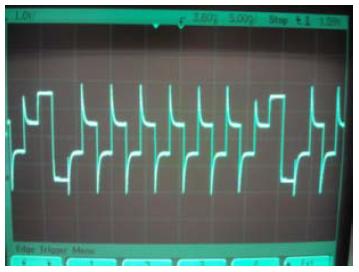
my problem is that when I makes some segments ON then other few segments becomes dimmed ON.

I checked on the DSO , I found that there is increase in the little voltage on the COMS which are off.

So how to avoid this problem. I tried by changing the constrast voltage(LCDCVCTL = LCDCPEN | VLCD_2_96), changed it

from 2.6 V to 3.34V  but the same problem occurs. Also tried by changing the frequency (LCDCCTL0) .
Waiting for remedy.
Thanks in advance.
Somnath Barge
  • somnath barge said:
    when I makes some segments ON then other few segments becomes dimmed ON.

    For multiplexed LED pins,  ON segments require an AC voltage while OFF segments won't. However, this is impossible to do. So the controller uses a complex pattern of voltages for COM and Semgnets signals, so there is as much difference between the ON signal and the OFF signal as possible. The users guide shows this pattern. But this means htat even off segments get some voltage. It is your job to adjust the voltages (and therefore the contrast) so that ON segments are sufficiently on and OFF segments are sufficiently OFF.

    If you want maximum ON/OFF separation, you cannot do multiplexing. That's a physical limitation of passive LCD and nothing the MSP could overcome.

  • Dear Sir,

    Following are the images I have added to show the problem.

    First image show less noise on the COMS when the less segments are ON.

    So how to eleminate this problem. 

    Thanks in advance.

    Somnath Barge

  • Dear Sir,

    In my previous post I have shown the image for less segments ON. Now following is the 

    image when we increse the ON segments the noise on the COMS is increasing. This 

    makes the OFF segments dimmed ON.

    How to avoid such noise on the COMS.

    See the IMage

    I have used internal biasing(1/3) . I tried by changing the contrast voltage by using the VLCD

     LCDCVCTL = LCDCPEN | VLCD_2_96 ;//| LCD2B_L;

    but the problem is not solved.

    Thanks in advance

  • I see the problem. Well, this isn't noise, this at first glance looks like some unexpected overshooting when switching the multiplex phases.

    I have no idea where it comes from but it shouldn't be there at all. Most surprising are the negative peaks after the large rectangular signal which cannot be explained by overshooting at all. Also, there is some charge time (no keen edge).

    What is your ground reference for the scope shots? Sometimes a wrongly chosen GND point lets us see things that aren't there ate all - or are different than we see them, which makes debugging difficult.

    If I had to make a guess, I'd say it looks like a diode (or transistor) on the switching stage that doesn't block fast enough or has a huge capacitance, so it lets a peak of maximum votage through when voltages are switched, depending on total load. What is your VCC? Did you forget some required blocking caps on the voltage generation? Just guesses.

  • Dear sir,

    I have used internal biasing to generate the voltages. So as per their recomdation used the 4.7uf capacitor.

    The waveforms are with respect to my gnd.

    No problem is solved still.

    Thanks in advance

    Somnath Barge

  • somnath barge said:
    No problem is solved still.

    I'm sorry, but I have no more ideas. I don't have a 4x or 6x chip myself (never used glass LCD), so I cannot compare with my devices.

    Those peaks look very strange and I wonder how they are produced. I can only suggest checking all related (supply) voltages whether similar peaks appear there during operation. If so, try to block them with additional capacitance.

**Attention** This is a public forum