This thread has been locked.

If you have a related question, please click the "Ask a related question" button in the top right corner. The newly created question will be automatically linked to this question.

12V input interface to MSP430 using ULN2003


Hello,

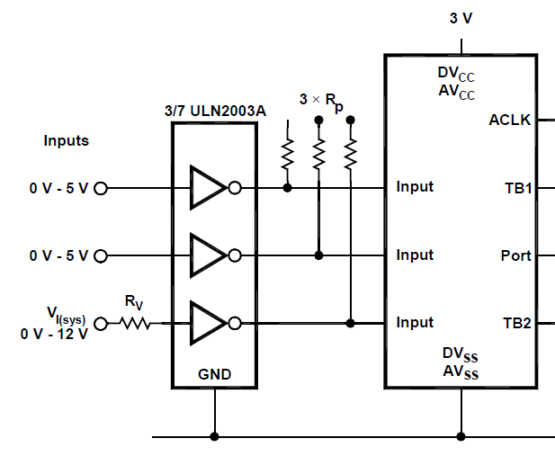
As mentioned in the application note - Input interface 3V & 5V circuit to MSP430 - (link here), I am trying to use ULN2003 to input interface a 12V circuit to MSP430.
I have tried the circuit as given in the doc.

Where should the "COM" terminal of MSP430 be connected? (not given in the doc)
I have tried these combinations

1) Connecting COM to 3.3V --> output of ULN at 3.3V at 12V input (no change if input is changed)
2) Connecting COM to GND --> output of ULN at 0.8V at 12V input (output 0 if input at 0V)
3) Not connecting COM         --> output of ULN at 3.3V at 12V input (no change if input changed)

Has anyone successfully interfaced this way? If not, is there any low cost alternate way?

--Shashank

  • Shashank Revankar said:
    application note - Input interface 3V & 5V circuit to MSP430 - (link here),

    That link doesn't work. Do you mean this:

    Application Report  SLAA148 – October 2002

    Interfacing the 3-V MSP430 to 5-V Circuits

     http://www.ti.com/lit/an/slaa148/slaa148.pdf

    Shashank Revankar said:
    the circuit as given in the doc

    That looks like the left-hand half of  Figure 7 from page 12 - yes?

    Shashank Revankar said:
    Where should the "COM" terminal of MSP430 be connected? (not given in the doc)

    Which "COM" terminal?

    If no specific mention is made, then the general guidance from the User Manual and Datasheet should be used...

  • Hello Shashank.

    You mean COM pin of ULN not MSP, right? It should be connected to 3 V. Anyway, you can use a resistor + zener diode on each MSP input for simple one-way voltage converson.

    Best regards,

    Mikolaj

  • Andy

    Thanks for pointing out that. Link is fixed now.
    Its the same figure that you mentioned. Yes
    I am talking about the "COM" of ULN2003.

    Regarding datasheet, ULN2003 datasheet does not given any application diagram for this application. And I have tried the combinations mentioned in my post. 

    Mikolaj

    Yes I mean COM of ULN. I tried connecting to 3 V, but it does not give me output swing for change in input voltage.
    To be clear, I require 12V - > 3.3V and 0V -> 0V (I assume there aren't any other levels)

    The idea of zener sounds appealing, but I guess input current will affect zener (input current may go upto 500mA).
    However I will try that out. Thanks 

  • Shashank Revankar said:
    The idea of zener sounds appealing, but I guess input current will affect zener (input current may go upto 500mA).

    Well, if the MSP shall be an input, input current would be ideally zero. No matter how much the signal can source.

    The MSP has an internal 'variable zener diode', a so-called 'clamp' diode. It has a value of VCC+0.3V@2mA (which also is the maximum rated current) and is actually a schottky diode between pin and VCC. (there's a second, inversed clamp diode to GND, limiting the input to GND - 0.3V in the other direction)

    Now if you have a series resistor that has a voltage drop of (Vin-Vcc) at a current of <2mA, then you don't need the ULN or a zener diode.

    In case of 12V input signal and VCC=3V, then you need a voltage drop of 9V on 2mA or less, so you need a series resistor of 4,5k or more. Of course this means a current of 2mA if the input has 12V. You can lower it by picking an even higher series resistor. 9k = 1mA, 90k = 100µA. The input impedance of the MSP port pin drivers is high enough for such a high series resistance.
    For 5V input, you only need a voltage drop of 2V, so 1k is the minimum series resistor you need.

  • Thanks Jens-Michael Gross. Your answer clarified lots.

    Jens-Michael Gross said:

    Now if you have a series resistor that has a voltage drop of (Vin-Vcc) at a current of <2mA, then you don't need the ULN or a zener diode.

    However is it advisable to take some precautionary measure? As the input will be from automotive electronic systems, I am not really sure about the way it handles current.

    Shashank

  • Worst case is that output voltage drops due to output impedance. Which is what you want :)

    Well, using a zener diode would also cause current (when used to short the input voltage to GND). And if in series, you won't see much of a voltage drop on it if there isn't some current too. Most zeners require some mA to show the specified voltage drop. on small currents, the voltage drop is much smaller. So after all, you'll still get an equilibrium only when currents and voltage drops fit.

    The only way to protect the inputs without wasting current, is to provide a dedicated level shifter circuit made of some transistors whcih in turn require some current too, and also space and money.

    I used a series resistor a lot for input protection and never had a problem. And our devices are running in industrial environment, which is not too much nicer than automotive.

  • Jens-Michael Gross said:

    I used a series resistor a lot for input protection and never had a problem. And our devices are running in industrial environment, which is not too much nicer than automotive.

    Thanks a lot. 
    Now I am confident to go ahead with a series resistor!! 
    Shashank

**Attention** This is a public forum