This thread has been locked.

If you have a related question, please click the "Ask a related question" button in the top right corner. The newly created question will be automatically linked to this question.

Error connecting to the target: Unknown device

Other Parts Discussed in Thread: MSP430F2481, CODECOMPOSER

Hello,

I am taking over development for our MSP430F2481 and I am having problems with CodeComposer/MSP-FET430UIF. I receive the message "Error connecting to target: Unknown Device" - which unfortunately is quite common from what I've seen in this community.

Here are a few details about my configuration:

CodeComposer:  v5.3.0.0090

MSP-FET430UIF: v1.4a with firmware 3.02.05.004 installed (via Elprotronic configuration utility)

Target Board: MSP-TS430PM64 with modifications for external power.  I have tested for the proper 3.3V signal according to the Hardware User's Guide.

Here is what I have done up to this point:

1.) I had a working setup using the new DLL package (3) and an older version of CodeComposer.  I tried to downgrade to DLL 2 to get my debugger working with our latest version of CrossWorks studio.  I used the Texas Instruments->MSP-FET430UIF Debug Interface->MSP-FET430UIF v3 to v2 Downgrade utility to do this.  This didn't work with CrossWorks, so I tried to get it working again with CodeComposer.

2.) I upgraded the MSP-FET430UIF to the latest version of firmware using the Elprotronic utility (described above).

3.) I completely uninstalled CodeComposer and installed the latest version (described above).

4.) I am able to check the firmware version of my MSP-FET430UIF using the Elprotronic utility.  I can also read the flash.  When I try to send the .hex file using this utility I get the message "JTAG communication initialization....     failed"

5.) I checked the COM port setting and I am connected to COM5(CDC).

My question:

Is there any additional advice you can give for troubleshooting my configuration? I have read several posts, and I have been working this problem for two days now.  Is there a way to know for sure that the MSP-FET430UIF has been corrupted?  I have the feeling that using your software has somehow broken my debug interface.

Any advice would be greatly appreciated. I am growing rather frustrated.

  • Justin Meulenberg said:

    Is there any additional advice you can give for troubleshooting my configuration?

    What happens when you try to erase the flash on your MSP430F2481 in the MSP-TS430PM64 using the FET-Pro430 Lite and your MSP-FET430UIF?

    MSP 430FG439-debugging problem

  • I receive the error

    =====================================
    JTAG communication initialization....     failed
    Verifying Security Fuse ....................     failed
     --------------- FAILED !!! -----------------

    It is the same error I receiver when I try to load the code using the Elprotronic software.  I am using WIndows XP, by the way.

  • What was your motivation for providing external power to the MSP-TS430PM64?  Are you powering the MSP-TS430PM64 externally while you are trying to program it using the MSP-FET430UIF?  The MSP430F2481 can be powered from the MSP-FET430UIF during programming. 

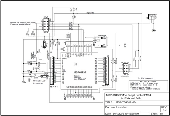
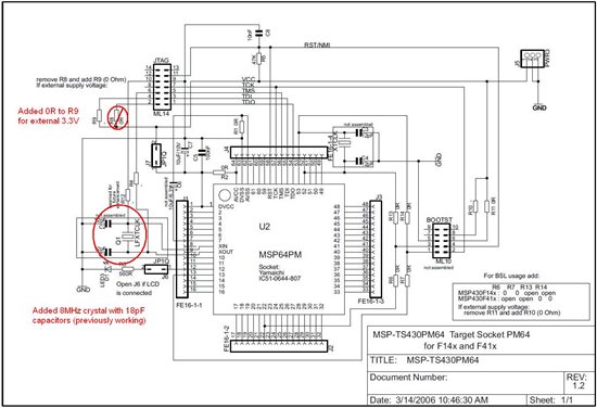
    What changes did you make to the MSP-TS430PM64?  I've attached a copy of the schematic.  If you could mark it up with yoru modifications, it might be more clear.

  • I removed the 0R resistor from R8 and placed a new 0R resistor on R9.  I am powering the target through J5 (VCC - 3.3V, GND -GND).  This configuration was working a week ago.

  • What results do you get when you remove these modifications and revert the MSP-TS430PM64 back to the original schematic?

  • I revert back to the original schematic and I get the same error.

    I have been monitoring the signal lines on the JTAG and this is what I see:

    VCC - Power looks good.  When I click the POWER ON/OFF BUTTON in the Elprotronics software it toggles between 3.3V and ground (as expected).

    RST - With the POWER ON, it always stays at 3.3V. POWER OFF it always stays at ground. When I click the RESET button in the software the state doesn't change.  When I attempt to program, I see a square wave. After it fails programming, it always remains at 3.3V.

    TCK - Same behavior as RST.  I can see a couple of lows when it attempts to program, then it is constantly held in the HIGH state until I restart the software

    TMS - Start in the LOW state. If I POWER ON device using the software, it goes HIGH. When I attempt to program, I see a slow sequence of HIGH and LOW.

    TDI - Same as TMS...slightly different sequence of HIGH and LOW during programming

    TDO - Starts HIGH. During programming, it looks terrible.  It goes from HIGH to LOW but does not make it to 3.3V on some occasions.  It looks like this is a much faster signal and looks very noisy in general.

    Please advise.

  • To confirm,  you have oriented pin 1 like this, correct?


  • Yes, Pin 1 is in the correct orientation.  I am pretty sure my debugger was damaged somehow during the firmware loading process. I will try to get this replaced, I can't spend any more time trying to troubleshoot this.

  • Okay, let me know if replacing it solves the problem. 

**Attention** This is a public forum