This thread has been locked.

If you have a related question, please click the "Ask a related question" button in the top right corner. The newly created question will be automatically linked to this question.

Multiple Buttons in MSP430G2553 with asm

Other Parts Discussed in Thread: MSP430G2553, L293D

Hi 

I want to some basic projects with msp430g2553. I bought msp430 launchpad.

and I write some codes.

This is my code.

#include "msp430G2553.h"
;-------------------------------------------------------------------------------
ORG 0F800h ; Program Reset
;-------------------------------------------------------------------------------
RESET mov.w #0280h,SP ; Initialize stackpointer
StopWDT mov.w #WDTPW+WDTHOLD,&WDTCTL ; WDT Durdur
SetupP1 mov.b #001h,&P1DIR
mov.b #008h,&P1OUT ; P1.3 set, else reset
bis.b #008h,&P1REN ; P1.3 pullup
bis.b #008h,&P1IE ; P1.3 Interrupt enabled
bis.b #008h,&P1IES ; P1.3 hi/low edge
bic.b #008h,&P1IFG ; P1.3 IFG Cleared
bis.b #010h,&P2IE ; P1.3 Interrupt enabled
bis.b #010h,&P2IES ; P1.3 hi/low edge
bic.b #010h,&P2IFG ; P1.3 IFG Cleared
;
Mainloop bis.w #LPM4+GIE,SR ;
nop
;
;-------------------------------------------------------------------------------
P1_ISR;
;-------------------------------------------------------------------------------
xor.b #001h,&P1OUT
bic.b #008h,&P1IFG ;
reti
;-------------------------------------------------------------------------------
P2_ISR;
;-------------------------------------------------------------------------------
xor.b #001h,&P1OUT
bic.b #010h,&P2IFG
reti ;
;
;-------------------------------------------------------------------------------
; Interrupt Vectors.
;-------------------------------------------------------------------------------
ORG 0FFFEh ; MSP430 RESET Vector
DW RESET ;
ORG 0FFE4h ; P1.x Vector
DW P1_ISR
ORG 0FFE6h ; P1.x Vector
DW P2_ISR ;

END

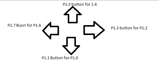
When I am using one button I have no problem. But I wont to more buttons. Example in my code. When I use P1.3 button. P1.0 active or I pressed P1.4 button P1.0 active.

But I am doing P1.3 button but P1.4 button isnt working. 

Thanks u

  • All pins on P1.x share one interrupt vector.

    If you only want one pin at a time, you could enable just one one pin that triggers a interrupt (P1IE)

    But if you want multiple  pins, your interrupt routine would have to read the P1IFG register to see what pin created the interrupt.


    Port P1 resistor enable: P1REN 027h

    Port P1 selection: P1SEL 026h

    Port P1 interrupt enable: P1IE 025h

    Port P1 interrupt edge select: P1IES 024h

    Port P1 interrupt flag: P1IFG 023h

    Port P1 direction: P1DIR 022h

    Port P1 output: P1OUT 021h

    Port P1 input: P1IN 020h


  • Hi,

    The following lines in your code are setting/clearing bits for P2.4, not P1.3 or P1.4:

    bis.b #010h,&P2IE ; P1.3 Interrupt enabled
    bis.b #010h,&P2IES ; P1.3 hi/low edge
    bic.b #010h,&P2IFG ; P1.3 IFG Cleared

    Also, the launchpad doesn't have a button connected to P1.4. Have you connected a button to P1.4 yourself or are you wanting to use the right-hand button on the launchpad board?

  • I want this. A car when I press button forward or back or right or left. I want this.

  • Read Section 8.2.7 (page 339) of the User's Guide http://www.ti.com/lit/ug/slau144i/slau144i.pdf

    When you read P1IFG register, you need to test the bits to see which pin generated the interrupt. Then based on that take whatever action it is you want.

  • I read it saying only two interrupts I will do? 

    All ports 1 connected 1 interrupt. What do I do?

  • Selim Erkan Oguz said:

    I want this. A car when I press button forward or back or right or left. I want this.

    What you want to do is reasonable and can be realized. But you need to do two things right. (1) You need to connect additional components to the LaunchPad board. (2) You need to load the chip on the board with software.

    It is not clear if you did (1) or not. And it is clear that you did (2) incorrectly.

    On second thought, actually, you do not even need a MSP430 (or any microprocessor). Simply remove the MSP430 and insert 4 jumper wires in that socket, One connects P1.0 with P1.1, another connects P1.2 with P1.3, a third one connects P1.4 with P1.5, and the fourth one connects P1.6 with P1.7. In this case, you still need to do (1), but (2) is optional and it does not matter at all.

  • old_cow_yellow said:
    On second thought, actually, you do not even need a MSP430 (or any microprocessor).

    Not quite the same if you look at what he is doing. That would only light the LED when the button is pressed. Not toggle it as I think he wanted to do. And besides, the OP comes across as a student who is tackling a class project in programming. Your solution doesn't really inspire the learning of programming.

  • Selim Erkan Oguz said:

    I read it saying only two interrupts I will do? 

    All ports 1 connected 1 interrupt. What do I do?

    No, that is not correct. All port 1 pins (that have their interrupt enabled) will generate 1 interrupt request to the ISR. However, when you read the P1IFG register (at address 0x0023) you will get an 8-bit word, and each bit represents one of the 8 Port 1 input pins (bit 0 tells if P1.0 generated the interrupt, bit 1 for P1.1, bit 2 for P1.2 and so forth).

    So, in your one ISR, you need to read the P1IFG register and look at which bits are set and take the appropriate action.

    in pseudocode:

    ISR {
    flags = P1IFG;
    if (flags & BIT0) {
    do bit0 stuff here;
    }
    if (flags & BIT1) {
    do bit1 stuff here;
    }
    ......
            if (flags & BIT7) {
    do bit7 stuff here;
    }
    } END ISR

    Hope that helps answer your question.

  • If you only are interested in toggling a LED when corresponding button is pressed.
    and as you have bits X_X_X_X_ for inputs that
    have the LEDs bits    _X_X_X_X for outputs.
    A simple shift right should do.


    P1_ISR;
    ;-------------------------------------------------------------------------------
    mov.b &P1IFG,R8  
    rra.b R8 
    xor.b R8,&P1OUT
    bic.b #0FFh,&P1IFG
    reti

  • Im triying this. Thank u

  • hi again

    Thanks for your helps. I try assembly but I didn't. I will try this code. I write it with C.

    This is my code.

    #include "io430.h"
    #include "in430.h"

    void main( void )
    {
    WDTCTL = WDTPW + WDTHOLD;

    DCOCTL=CALDCO_1MHZ;
    BCSCTL1=CALBC1_1MHZ;

    P1DIR = 0x00;
    P1REN = 0xFF;
    P1OUT = 0xFF;
    P2OUT = 0x00;
    P2DIR = 0xFF;

    while(1)
    {
    P2OUT = P1IN;
    }
    }

    Now showing everything now ok. But i use simulate. I didnt use with project now. I have l293d for motor control. 

    Thanks again

  • Endless loops are not nice (for the battery that is)

    You have interupts, use them.


    Or at least use watchdog timer to only check buttons 122 times/second and the msp430 spends the rest of the time in deep sleep.


     The l293d is so 1986, TI have new modern dual hrbridges (though if DIP is your choice, there is limits on how modern)


**Attention** This is a public forum