This thread has been locked.

If you have a related question, please click the "Ask a related question" button in the top right corner. The newly created question will be automatically linked to this question.

SPI STE functionality confusion?

Guru 15580 points

As I understand it, the USxSTE pin functions as a "chip select" for the slave device in a SPI connection (although not in the traditional sense). Based on the SLAU144I, the slave output should be muted if  USxSTE is set to slave-inactive.

16.3.4.1 Four-Pin SPI Slave Mode
In 4-pin slave mode, UCxSTE is used by the slave to enable the transmit and receive operations and is
provided by the SPI master. When UCxSTE is in the slave-active state, the slave operates normally.
When UCxSTE is in the slave- inactive state:
• Any receive operation in progress on UCxSIMO is halted
• UCxSOMI is set to the input direction
• The shift operation is halted until the UCxSTE line transitions into the slave transmit active state.

However, this does not appear to be happening in my Launchpad testing.

I have set UCMODE to UCMODE_2 and mode to SPI slave.

The SPI output works properly when I use STE=low as an chip select (CSN in the snapshot below):

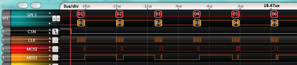
However, since I have other SPI devices on this bus, I want the MSP430 to be disabled when I set CSN (chip select negative) high (inactive). But this does not seem to work properly. In the snapshot below I hold CSN high, but the spi slave (MSP430) continues to send data to the bus.

AM I MISUNDERSTANDING THE FUNCTIONALITY OF THE USxSTE PINS? Is there some configuration parameter I am missing? Any suggestions would be appreciated.

  • Mystery solved.

    I was relying on Grace to properly set the P1SEL & P1SEL2 pins when I selected 4-wire SPI slave mode. However, apparently you must manually select these pins in the I/O port configuration section of Grace. This is a bit confusing.

    All is now working properly after properly setting the PxSEL pins.

  • MikeH said:
    AM I MISUNDERSTANDING THE FUNCTIONALITY OF THE USxSTE PINS?

    Yes. STE is no chip select. It is a 'shut up' control for the MSP in slave mode (or to turn the USCI in slave mode if it is currently master in a multi-master environment.

    It does not init the high-level protocol, synchronize to a byte-border, clear the shift register, trigger an interrupt or anything else. You need to check the input state in your software and reset/init the USCI manually.

    This in addition to the observation that apparently GRACE doesn't switch the port pin to STE module usage, despite of UCMODE_2.

  •  STE is no chip select

    Turns out, it performs exactly the same functionality as a traditional "chip select" in traditional SPI applications.

    Why the TI MSP430 documentation talks about  "multiple master" scenarios is beyond me. The only traditional SPI applications that I am aware of consist of a single master and multiple slaves. In fact, other TI products (I am most familiar with the C55xx) document "chip select" or "slave select" in the SPI interface. It could be that TI is trying to avoid using Motorola terminology (MISO, MOSI, CSLK, SS#) as many other chip manufacturers do, since Motorola invented the SPI interface definition.

  • MikeH said:
    Turns out, it performs exactly the same functionality as a traditional "chip select" in traditional SPI applications.

    Sorry, I cannot locate the 'traditional chip select funcitonality' anywhere in the article.

    However, the typical chip select goes beyond the funcitonality of STE: it resets the state machine, synchronizes to a byte border (on devices with byte-wise transfer), resets the high-level protocol, or on de-assert the received bitstream is interpreted/latched and executed (e.g. "the last n bits count").

    STE just does one thing: it makes the slave deaf and silent. When it is asserted again, the slave will continue where it was, even mid-byte. The application won't notice at all (no interrupt. The communication simply doesn't continue as long as STE is de-asserted)

    MikeH said:
    Why the TI MSP430 documentation talks about  "multiple master" scenarios is beyond me.

    Because in 4-wire master mode, STE will turn the master into slave when another master (the primary master) pulls it.

    MikeH said:
    since Motorola invented the SPI interface definition

    Did they? AFAIK, they just have given an existing nameless class of communications protocols a name. But SPI itself has existed before in probably not less variations as it exists now under the name SPI.
    That's the reason why it isn't standardized like the I2C (which was invented by Philips/Valvo)

**Attention** This is a public forum