This thread has been locked.

If you have a related question, please click the "Ask a related question" button in the top right corner. The newly created question will be automatically linked to this question.

RS485 with a MSP430FG4619

Other Parts Discussed in Thread: MSP430FG4619

Hi,

I'm trying to use a stepmotor (PD3-110-42-485) with an MSP430FG4619.

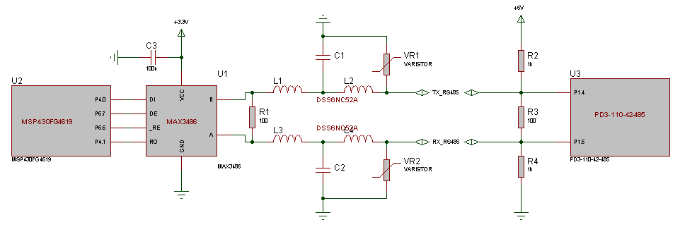
The communication is made with RS485 throught a MAX3486 and it is connected to P4.0/P4.1 pin. The MSP430FG4619 has a 32khz and 8Mhz crystal.

I manage to send command to the stepmotor (the motor rotate) but I have difficulties to get a proper reply.

The initialisation for the uart is :

     P4DIR |= (BIT0);
  P4DIR &= ~(BIT1);

  P4SEL |= BIT0+BIT1;

  P6DIR |= (BIT7+BIT6);
  P6SEL &= ~(BIT7+BIT6);

  RS485_DE(0);
  RS485_RE(0);

  U1CTL |= SWRST;

  // parity='none', stopbits=1, address=1,
  // CHAR : bits=8

  U1CTL |= CHAR;                         // 8-bit character
  U1TCTL |= SSEL0;

  // baud=9600
  U1BR0 = 0x03;
  U1BR1 = 0x00;

  U1MCTL = 0x4A;                            // Modulation

  ME2 &= ~(UTXE1 + URXE1);                     // Diseable USART1 TXD/RXD

  U1CTL &= ~SWRST;                          // Initialize USART state machine

Since I manage to make the motor move, I don't think there is a problem there.

There communication is made like this :

   unsigned long wait;

  RS485_DE(1);
  RS485_RE(0);

  ME2 |= UTXE1;                     // Enable USART1 TXD

  for(int i=0;i<9;i++)
  {
    moteur.reply.data[i] = 0;
  }

  moteur.ready = FALSE;

  for(int i=0;i<9;i++)
  {
    while(!(IFG2 & UTXIFG1));
    U1TXBUF = moteur.command.data[i];
  }

  while(!(U1TCTL&TXEPT));

  moteur.reply.data[0] = U1RXBUF;    // remove possible data in buffer

  ME2 &= ~UTXE1;                     // Diseable USART1 TXD
  ME2 |= URXE1;                     // Eneable USART1 RXD

  RS485_DE(0);
  RS485_RE(0);

  for(int i=0;i<9;i++)
  {
    wait = 0;

    while((!(IFG2 & URXIFG1))&&(wait<0xFFFFF)) { wait++; }

    if(wait>=0xFFFFF) { moteur.reply.data[i] = 0; }
    else moteur.reply.data[i] = U1RXBUF;
  }

  ME2 &= ~URXE1;                     // Diseable USART1 RXD

  for(int i=0;i<9;i++)
  {
    usb_writeByte(moteur.command.data[i]);
    usb_write('-');
  }

  usb_writeStr("\r\n");

  for(int i=0;i<9;i++)
  {
    usb_writeByte(moteur.reply.data[i]);
    usb_write(':');
  }

  usb_writeStr("\r\n");

I'm not sure with the while(!(U1TCTL&TXEPT));

The "usb" is a rs232 communication with a PC to help me to debug (UCA0).

So I got on the PC :

01-09-4B-00-00-00-00-C8-1D-
64:09:00:00:00:C8:38:00:00:
BAD
01-09-4B-00-00-00-00-C8-1D-
64:09:00:00:00:C8:38:00:00:
BAD
01-09-4B-00-00-00-00-C8-1D-
64:09:00:00:00:C8:38:00:00:
BAD
01-09-4B-00-00-00-00-C8-1D-
64:09:00:00:00:C8:38:00:00:
BAD
01-09-4B-00-00-00-00-C8-1D-
64:09:00:00:00:C8:38:00:00:
BAD
01-09-4B-00-00-00-00-C8-1D-
02:01:64:09:00:00:00:C8:38:
OK
01-04-01-00-00-00-4E-20-74-
64:04:00:00:4E:20:D9:00:00:
BAD
01-09-4B-00-00-00-00-C8-1D-
00:00:C8:38:00:00:00:00:00:
BAD
01-04-01-00-FF-FF-B1-E0-95-
64:04:00:00:00:00:6B:00:00:
BAD
01-04-01-00-00-00-4E-20-74-
64:04:00:00:4E:20:D9:00:00:
BAD


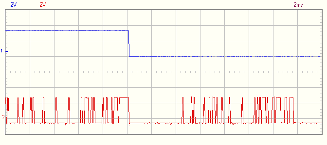
The reply should be 01:02:64:XX:XX:XX:XX:XX:XX. So most of the time, I miss 2 bytes and even 4 bytes in some case. The worst is that the first command is to specify a delay between the command and the reply...

Is there a problem on the MSP430 side or should I investigate more on the motor side ?

  • Since RS-485 is a half-duplex physical interface, my first suspicion would be that the driver-enable and receiver-enable control signals aren't being switched soon enough.

    Have you looked at the signals on the board to check the timing between releasing DE and when the motor controller responds to the MSP? That would be my first step in narrowing down the issue.

  • I have verify all line :

    - synchronization of DE / TX : OK

    - synchronization of DE / RX : OK (the moteur take into account the delay command); the number of byte send seems good.

    - A / RO on the MAX3486 : OK

    Nothing seems wrong from either sides. What can be wrong on the RX on the MSP side ?

  • A little progress : I have enable URXEIE to be able to see what byte are skipped.
    The reception always start with a BREAK error then a Framing Error with the 2 first bytes packed in 1 byte. When there is no Framing Error, the 2 first bytes are correct.

    So I think there is a problem on the receive buffer when I switch the DE line. I have try to insert a delay between the change on the DE and enabling received, but with no luck.

  • Hi Bruce,

    please note, when the receiver is disabled (URXEx = 0), re-enabling the receiver (URXEx = 1) is asynchronous to any data stream that may be present on URXDx at the time. Maybe you enable the receiver too late. Do you really have to turn the receiver off in between?

    Best regards,
    Christian

  • Hi,

    I disable/enable receiver since there is an echo with TX. Even when I don't disable it, I still have the problem.
    The motor is set to send a message 15ms after it received the last byte of the command.  I have confirmed it by looking at the signal on the RS485 line.

    I have try to enable/reable received, reset the UART (U1CTL |= SWRST; U1CTL &= ~SWRST;) after I set DE to 0 but nothing works.

    I didn't find any sample code for MSP430 for a RS485. Does anyone know one ?

  • Bruce ROLLAND said:
    I disable/enable receiver since there is an echo with TX. Even when I don't disable it, I still have the problem.

    Then maybe problem is somewhere else? Did you check for baudrate or polarity mismatch?

    Bruce ROLLAND said:
    I didn't find any sample code for MSP430 for a RS485. Does anyone know one ?

    RS485 is half-duplex. So if you have enough hardware capacity/resources to receive your own bytes and discard them - then do it, do not bother switching receiver on/off. For applications w/o multitasking I do it very easy: immediately after each TX I poll for incoming byte and discard it. In case of IRQ's it's sligtly more complicated.

  • Bruce ROLLAND said:
    So I think there is a problem on the receive buffer when I switch the DE line.

    What is the RX line state when the receiver is deactivated? is it pulled high or is it open?
    If the bus isn't properly terminated, then line reflections may cause an erroneous start bit that is caught when you switch the receiver on too early. Or you switch it on too late and miss the real start bit, so the byte starts at the first low bit after a high bit of the first byte.

    In one of our projects, I have enabled the receiver all the time, so it receives an echo of the own data as well as anything else. In most other projects (actually sub-projects of a big opne), I have added a delay of 2 ms before answering on the bus. So line reflections won't disturb and the receiver goes online after enough delay but before the answer begins. In this project, the RS485 is used as a star network, which isn't quite right, but the only way to implement the modular device structure. So bus termination isn't proper and significant reflections occur.

  • Hi,

    I have change the receiver to not desable it.

    for(int i=0;i<9;i++)
      {
        while(!(IFG2 & UTXIFG1));
        U1TXBUF = moteur.command.data[i];

        while(!(IFG2 & URXIFG1));
        conf[i] = U1RXBUF;
      }

    ...

    for(int i=0;i<9;i++)
      {
        wait = 0;

        while((!(IFG2 & URXIFG1))&&(wait<0xFFFF)) { wait++; }

        err[i] = U1RCTL&(FE|PE|OE|BRK);

        if(wait>=0xFFFF) { moteur.reply.data[i] = 0; }
        else moteur.reply.data[i] = U1RXBUF;
      }

    ...

    Same problem.

    I'm not use to polarity but it seem to be so. When I witch DE from 1 to 0 the RX do so.

    And I got :
    01(01)-04(04)-01(01)-00(00)-00(00)-00(00)-4E(4E)-20(20)-74(74)-
    00(80):00(10):A0(80):64(00):04(00):00(00):00(00):75(00):EC(00):

    First line, command : byte send (byte read) - ...
    Second line, reply : byte read (U1RCTL) : ...

    80 is a break error and 10 is a Framing error.

  • The red trace on the right side of the scope trace you posted looks like it is the wrong polarity. For NRZ encoding (standard on async UART) the idle state should be a logic high when looking at the CMOS side of the 485 transceiver.

    That to me would explain the break and framing errors.

    Which RS-485 chip are you using? Is it possible that you have the receive differential lines backwards? Can you post a picture from your schematic showing how that part of the circuit is wired?

  • There is the schematic.

    I use a MAX3486.

    The "TX_RS485" and "RX_RS485" goes to the motor. I have try to exchange the line that go to the motor but nothing works then.

  • Do you have the schematics for the other end of the circuit, at the motor? It still looks like inverted polarity on the data coming from the motor. Is that something that is selectable on the motor controller?

  • A lot of times, a RS485 half-duplex interface is also multi-drop, which needs to address devices before they respond. There are two modes in the MSP430 UART that do this. One is Address-Bit Multiprocessor Format, which sends 9 bit data instead of 8 bit. The 9th bit is used to flag whether the serial data being transmitted is an address or data. There is also a Idle-Line Multiprocessor Format which generates idle frames between transmit and receive packets and sends an address character.

  • The main problem was electrical. RS485 lines need a pullup and a pulldown in addition to terminators :

    With this, it works fine. I have changed the code to use IT :

    void moteur_StartCommand()
    {
      moteur.ready = FALSE;
      moteur.compt = 0;

      RS485_DE(1);
      RS485_RE(0);

      IE2 |= UTXIE1;
      IFG2 |= UTXIFG1; // Launch first IT
    }

    #pragma vector=USART1TX_VECTOR
    __interrupt void usart1_tx (void)
    {
      if(moteur.compt<=8) // Byte to send
      {
        U1TXBUF = moteur.command.data[moteur.compt];  // Send byte
        usb_writeByte(moteur.command.data[moteur.compt]); usb_write('-');
        moteur.compt++;
      }
      else // All byte sent
      {
        IE2 &= ~UTXIE1;
        usb_write('\n');
        usb_write('\r');

        while(!(U1TCTL&TXEPT));                       // Wait end of emission

        moteur.reply.data[0] = U1RXBUF;               // Empty buffer

        moteur.compt = 0;
        RS485_DE(0);
        RS485_RE(0);

        IE2 |= URXIE1;
      }
    }

    #pragma vector=USART1RX_VECTOR
    __interrupt void usart1_rx (void)
    {
      unsigned char i = moteur.compt;
      moteur.reply.data[i] = U1RXBUF;

      usb_writeByte(moteur.reply.data[i]); usb_write(':');

      moteur.compt++;

      if(moteur.compt>=9)
      {
        usb_write('\n');
        usb_write('\r');

        moteur.ready = TRUE;
        IE2 &= ~URXIE1;
      }
    }

    In my test program, it works fine but for the first command. I will have to do some more tests.


    Thanks to everyone for helping me.

  • Bruce ROLLAND said:
    RS485 lines need a pullup and a pulldown in addition to terminators :

    Not exactly in addition. Pullup/pulldown are on one side of the bus, terminators on the other end (if all peers aren't moee than a few cm from the bus). RS485 isn't really suited for a star design (with a terminator on every peer) even though we use it this way without too many problems.

    In any case, R3 is superfluous an only increases the current consumption.
    Also, the combination of pullu/pulldown and terminator resistance causes an idle voltage of only 0.23V on the differential lines (0.115V if R1 and R3 are populated). Probably not enough to ensure a stable idle signal on a distorted bus.

    You should really raise R1 and remove R3. Or, if you really need that strong a termination, lower R2/R4. But keep an eye on the maximum driving capability and slew rate of your RS485 driver.

**Attention** This is a public forum