This thread has been locked.

If you have a related question, please click the "Ask a related question" button in the top right corner. The newly created question will be automatically linked to this question.

Software-driven boost converter to power msp430 itself (let's build)

Guru 46710 points
Other Parts Discussed in Thread: TPS61220, MSP430F249

How to start.. Whatever. Let's talk about this.

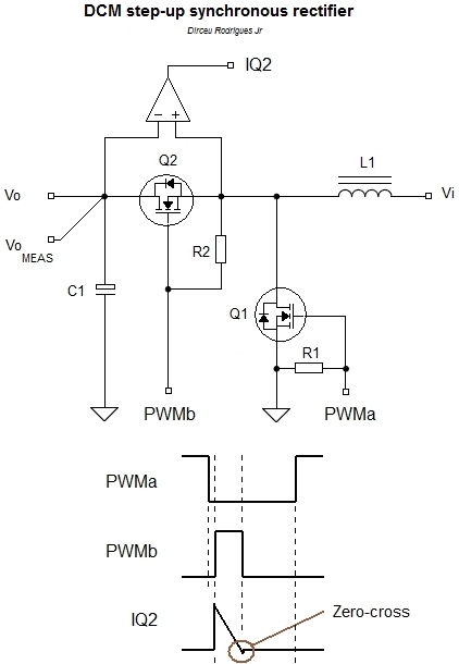
There's around microcontrollers with boost converters built-in which allows to boost power supply voltage from 0.7V to (3V) operating VCC of uC. They cost money and they are not msp430 (G-series). Actually question is not about picking right piece of silicon for low voltage application but having fun building useful stuff out of virtually nothing. We can build boost converter using PWM peripheral, MOSFET, inductor and Schottky diode. Energy storage capacitor will be helpful indeed. All what's needed - proper control of PWM to sustain target (3V) voltage all the time. Simple, isn't it?

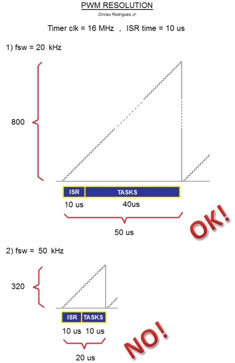
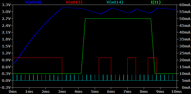
So here's application: we have G-series msp430 (2553?) with boost converter which powers microcontroller from disposable ~3V battery, we need to squeeze all we can get out of it. The closer battery gets to 0V still operating uC at 3V - the better. Allowed VCC range is 2.5-3.3V. Application have ultra low power sleep time when RTC using 32kHz fork oscillator shall be running, then there's "high power" moments when microcontroller shall calculate something, light LED or even sustain power for RF transceiver. For starter let's assume that high power means 20mA at 3V and lasts 10ms, then whatever... 1 or 60 minute low power which shall consume close to nothing. Immediately I see two main problems here: how to measure VCC voltage most energy-efficient way and how to control PWM such a way that we don't overshoot or undershoot target 3V VCC no matter how big or small consumption is. During low power state PWM for sure can be off but we need to wake-up in time to charge capacitor. Otherwise we are dead. Question is - how we determine when to wake-up from low power to start PWM for capacitor recharge? Measure or estimate or both? How? During high power state we need to drive boost converter such a way so VCC voltage does not go outside defined (2.5 - 3.3V) boundaries. This is most challenging part I think.

For sure I have some ideas and considerations which I will share later but I am eager to hear yours first.

p.s. Those who are sceptical, not interested or simply in bad mood - please do not waste electronic ink of The Internet :)

  • My design, to be published in a magazine soon.

  • Rodrigues said:
    My design, to be published in a magazine soon.

    Well done! I just wonder why series diode if you are doing synchronous rectifier?

  • Even if your booster converter is 100% power efficient, the over all power efficiency is very poor near the end-of-life of the battery due to the internal resistance. You want to squeeze all we can get out of it. You might end up with squeezing the remaining life of the battery without getting much out of it.

    When you boost the voltage up by a factor of x, the current drain from the battery will increase by a factor of x (for a 100% efficient booster, even more if not 100%). This cause the power wasted inside the battery to increase by a factor of x-squared. Furthermore, the battery open-circuit voltage will drop making it necessary to increase x. The battery internal resistance will increase. Both of these will worsen the situation far beyond x-squared.

  • old_cow_yellow said:
    Even if your booster converter is 100% power efficient, the over all power efficiency is very poor near the end-of-life of the battery

    Sure! Key here is definition of "near the end-of-life of the battery" for device itself and especially for consumer which mostly tend to end life of battery long before it's actually dead. Have you ever measured remaining charge of batteries consumers are throwing away? - You will be blown away when see results.

    Let me remind you that I "specified" VCC regulation range as 2.5-3.3 volts. It more or less means that if VCC drops below 2.5V, then most users will find performance of our imaginary device unsatisfying and tend to change battery if device does not have boost converter. Some consumers perhaps will do it at 2.7V already. This is more about regulation than getting battery voltage down to 0V.

    What do you suggest as most energy-efficient way to measure VCC during low power sleep? I see solutions; periodic ADC sampling, comparator (continuous or periodic enable/disable of CMP and divider), SVS, schmitt trigger. External voltage supervisors are disqualified due to cost. Schmitt trigger is very attractive but it's positive-going voltage spec is all over the place 1.35 - 2.25V for VCC=3V.

  • llmars said:
    Well done! I just wonder why series diode if you are doing synchronous rectifier?

        For sake of simplicity, my proposed converter is not based on synchronous rectification. The two leftmost MOSFETs (N and P channel) serve only to enabe/disable the converter. This is useful in a battery-powered system to avoid power consumption when the drive is off (eg start-up). Otherwise, there would be a direct path between input and output through the diode. Also is useful in the stages of development/debugging. When the converter is operating, pin P4.3 remains on high level.

        I decided to implement a DCM converter due to its advantages: High efficiency on light loads and design of controller made easier (the transfer function has a single pole - the second pole and RHP zero are insignificant). To use true synchronous rectifier, the complexity of the system is increased since it is usually required to detect the zero crossing current on high side transistor in order to turn it off (what happens when operating in DCM). I've been working on this application – see the figure below. Note that in this case both transistors are N channel, so the PWMb signal must be boostrapped to a higher voltage.

        Despite the MSP430 contain a flexible timer (mainly the up/down mode), believe in me: It would be difficult to ensure the correct polarity of involved signals under all conditions (eg startup, turning off the converter, duty-cycle changing and so on). Any errors could result in catastrophic consequences (remember that it is the MCU main power). All this only to save a fraction of the voltage drop caused by the replacement of a Schottky diode by a MOSFET. Efficiency comes at a price.

  • I was using two alkaline cells to power a G2553 running at 8MHz. When the voltage drops to 2.2V, the batteries need to be replaced.

    I check the Vcc/2 voltage periodically with ADC10 channel 11 using the internal 1.5V reference. It takes energy to check this, but I do not need to do it very often. The ADC reading starts with 1023 when the batteries are new, and drops slowly toward 750 when the Vcc is 2.2V. One potential problem of this method is, when Vcc is way below 2.2V, the ADC reading will be incorrect. I have not experienced this potential problem yet.

    If I had a good DC to DC converter to power the G2553 at 2.2V all the time, I could have doubled the battery life. With or without such a converter, about the same (small) amount of energy is discarded with the batteries. The difference is that the G2553 is more energy efficient in running CPU at lower voltage. At 3.3V the 8MHz CPU consumes 7mW, while at 2.2V it consumes 3mW.

    The desired converter need to (a) cost very little, (b) does not generate RF noise, and (c) very efficient when the G2553 is in active mode (~2mA) as well as in sleep mode (~2uA).

    Most ready made/designed converters cannot satisfy condition (c) above. A good design could also detect battery end-of-life too. Do you or anyone have suggestions?

  • old_cow_yellow said:
    Most ready made/designed converters cannot satisfy condition (c) above. A good design could also detect battery end-of-life too. Do you or anyone have suggestions?

    When I did research regarding subject, I found OnSemi NCP1400A attractive. Mostly due to price and availability. Well, yes it's not so effective as you may wish, even for "high load" current you specify, but you shall have a look anyway. Good thing that it have pulse-skipping mode for light loads and CE input which can be used to switch converter off so it consumes 0.6uA current. TI also have similar part with way better efficiency performance due to synchronous rectifier, TPS61220. Well done, TI !

    To conclude: best way to (nearly) satisfy condition (c) - to shutdown converter during LPM sleep and run on low leakage capacitor.

    old_cow_yellow said:
    I check the Vcc/2 voltage periodically with ADC10 channel 11 using the internal 1.5V reference.

    That was my initial idea. However I think periodical measurements using comparator can be even more power-efficient. What do you think?

  • Rodrigues said:
    All this only to save a fraction of the voltage drop caused by the replacement of a Schottky diode by a MOSFET. Efficiency comes at a price.

    There's other consideration - cost. Instead of building such a complex boost supply I would rather choose just TPS61220. My aim here is: either it's elegant, supercheap and supersimple or use dedicated parts like ready-made boost converter IC. Especially if it's about device that is not educational but for consumer market.

  • llmars said:
    There's other consideration - cost. Instead of building such a complex boost supply I would rather choose just TPS61220. My aim here is: either it's elegant, supercheap and supersimple or use dedicated parts like ready-made boost converter IC. Especially if it's about device that is not educational but for consumer market.

       I agree with you. The intermediate solution (using a specialized regulator controlled by MSP430), has the following additional advantages, besides the high safety, low cost and low complexity:

    _ Possibility to use a higher switching frequency. Traditional regulators work on hundreds of kHz or even MHz; which leads to low value inductors (tens of uH). Smaller  inductance leads to smaller size and cost. The output ripple may be lower, which also leads to low value filtering capacitors.

    _ Freeing the MCU processing load. This results in lower power consumption and simpler software. In this case it is also possible to reduce the clock frequency. Note that, in my projectMSP430F249 runs at 16 MHz (max)  and the switching frequency is 20 kHz, suitable to this MCU. 

       In fact ,converters implemented entirely in software are not suited to microcontrollers like MSP430. Best results can be obtained with real DSPs (as TMS320Fxx) or DSCs (as dsPIC33Fxx) which, in addition to high clock frequencies, have specialized peripherals (eg. high resolution PWM). My video is only intended to test the MSP430 limits and also an opportunity to apply control theory and signal processing.

    Good work.

  • Rodrigues said:
    switching frequency is 20 kHz

    Why so low freq? Why don't you do like 50 or 150 kHz? Can't keep-up with regulation speed?

    Rodrigues said:

    (using a specialized regulator controlled by MSP430), has the following additional advantages

    _ Possibility to use a higher switching frequency. 

    _ Freeing the MCU processing load. 

    - Low voltage start-up.

  • llmars said:
    Why so low freq? Why don't you do like 50 or 150 kHz? Can't keep-up with regulation speed?

         It's all about resolution. The higher the PWM frequency, the lower resolution available. Follow the figure below. Assuming Timer in Up mode, having a 16 MHz clock (no prescale). Also consider the controller running on ISR for 10 us (loop control). With a 20 kHz switching frequency, the maximum timer value is 800 (a slightly lower resolution than 10 bits), leaving 80% of free time to perform tasks from application. Now at 50 kHz, the maximum tiimer value is 320 (a resolution slightly better than 8 bits), leaving only 50% of free time to perform other tasks - more or less like every 2 instructions, one is dedicated to the controller. No way. It will be impossible running at 150 KHz, as you asked (due to timming and low resolution, the system could become unstable). The problem only gets worse changing the timer to Up/Down mode. In this case, for the same switching frequency, the resolution would be halved.

        For this reason, I made reference to specialized peripherals present in DSPs and DSCs (high resolution PWM units). 

        Serious "power converters based entirely in software": Use another processor.

  • Rodrigues said:
    Serious "power converters based entirely in software": Use another processor.

    If you need to build power supply with excellent load regulation (for unknown load) - then yes. But don't forget that your supply is part of closed system (supply+load) you are building - you have knowledge of load changes in advance most of the time. So you can use this knowledge for regulation. Such way you can build power supply which have quite slow loop regulation and for god's sake, don't need per-cycle regulation. Your supply can learn how to drive PWM for different levels of load that are coming and use this information too.

  • llmars said:
    ...Especially if it's about device that is not educational but for consumer market...

    llmars said:
    ...Such way you can build power supply which have quite slow loop regulation and for god's sake, don't need per-cycle regulation...

        Ok, maybe to build simple buck/boost converters to power string of LEDs and other small loads. On the internet there are many of them, mainly implemented with AVR, but not to power itself. As I showed, the 20 kHz value for MSP430 is just a good compromise between PWM resolution (too low will make the control system useless) and free time for the main task. Far beyond this frequency is simply unreliable (taking into account that, as you said, it is a commercial application). Just proof of concept.

    In my opinion, using a TPS6xx looks more promising, at least regarding the MSP430 as main MCU.

  • Rodrigues said:
    As I showed, the 20 KHz value for MSP430 is just a good compromise between PWM resolution (too low will make the control system useless) and free time for the main task

    Why you talk about CPU time here? Because software controlled sync rectifier plans? Otherwise it is not required to update PWM duty cycle each cycle meaning that CPU time for 20kHz and 150kHz PWM will be the same and supply stability too.

  • llmars said:
    ...is not required to update PWM duty cycle each cycle meaning that CPU time for 20kHz and 150kHz PWM will be the same and supply stability too.

       Even if you could perform the controller update say, every four or five PWM cycles, there's still the problem of PWM poor resolution. With a 150 kHz switching frequency, the maximum timer value (@ 16 MHz clk) is 106​​. That is, you will have no more than 106 different values for duty-cycle; a resolution close to 7 bits (not counting 0% and 100%). So, depending on the application, could result in an inadequate controller (big overshoots, instabilities, limit cycles, and so on). As I said, with a High Resolution Timer (present on DSP / DSC, but not on MSP430), this problem would be minimized.

  • Rodrigues said:
    That is, you will have no more than 106 different values for duty-cycle; a resolution close to 7 bits

    Have you ever heard of component named "big enough capacitor"? Also did you pay attention to my initial regulation specs (2.5 - 3.3V)? Other name of it: supply ripple voltage. Yes, THAT big. All this means that supply can have rough regulation and still be fine. I don't want my supply to have fast step load response either - no need.

    Rodrigues said:
    Probably result in an inadequate controller (big overshoots, instabilities, limit cycles, and so on).

    That's the main idea here - (have to repeat) that supply is integral part of device, it's regulation loop can/shall use estimated load information available to regulate most efficient way. Having properly sized capacitor and information about expected load, overshoots and other kind of instabilities can be avoided.

    PWM frequency is not so important actually, most probably I select "tradeoff" around 62.5kHz, 8 bits PWM.

  • Ilmars said:

    Most ready made/designed converters cannot satisfy condition (c) above. A good design could also detect battery end-of-life too. Do you or anyone have suggestions?

    When I did research regarding subject, I found OnSemi NCP1400A attractive. Mostly due to price and availability. Well, yes it's not so effective as you may wish, even for "high load" current you specify, but you shall have a look anyway. Good thing that it have pulse-skipping mode for light loads and CE input which can be used to switch converter off so it consumes 0.6uA current. TI also have similar part with way better efficiency performance due to synchronous rectifier, TPS61220. Well done, TI !

    To conclude: best way to (nearly) satisfy condition (c) - to shutdown converter during LPM sleep and run on low leakage capacitor.

    old_cow_yellow said:
    I check the Vcc/2 voltage periodically with ADC10 channel 11 using the internal 1.5V reference.

    That was my initial idea. However I think periodical measurements using comparator can be even more power-efficient. What do you think?

    [/quote]

    llmars,

    You misunderstood me. I was not looking for voltage booster, I was looking for buck regulator.

    I think when a 2-cell Alkaline battery drops to 2.2V, there is very little energy left. For the reason I stated in my previous posting, even a 100% efficient voltage booster can only salvage a small part of that small part of the total stored energy in the battery.

    Most of the total energy stored in that battery is already consumed when the voltage drops from 3.3V to 2.2V. I was looking for a way to utilize that major part more efficiently. To run G2553, I think a suitable Vout = 2.2V buck regulator can extend the battery life (from 3.3V to 2.2V) by up to 100%. Unfortunately, I cannot find such a buck regulator, the closest thing is LTC3549 from Liner Technology and I am not satisfied with it.

    --OCY

    I was looking for a more efficient way to use that majority of stored

  • llmars said:
    Have you ever heard of component named "big enough capacitor"? Also did you pay attention to my initial regulation specs (2.5 - 3.3V)? Other name of it: supply ripple voltage. Yes, THAT big. All this means that supply can have rough regulation and still be fine. I don't want my supply to have fast step load response either - no need.

       You will not achieve all the project requirements just by changing the output capacitor value. The design of a digital control system is somewhat more sophisticated. If you are lucky and the system works, you will not know how to explain it mathematically (the goal of engineering).

    But, good luck.

  • This is a horse of a different color.

    TPS61220 can be used to boost up the voltage of a single AAA alkaline cell to 2.2V and power a G2553 at 8MHz for about 400 hours in active mode.

  • old_cow_yellow said:
    This is a horse of a different color.

    And you pasture it in my garden :D

    old_cow_yellow said:
    TPS61220 can be used to boost up the voltage of a single AAA alkaline cell to 2.2V

    Oh, I am so sorry that I missed *your* 2.2V needs. Sure you need boost converter for single cell. On the other hand sadly that you miss to address what I am looking for.

  • Rodrigues said:
    The design of a digital control system is somewhat more sophisticated. If you are lucky and the system works, you will not know how to explain it mathematically (the goal of engineering).

    LOL thank you for giving this so valuable feedback. Good luck writing your article.

    Meanwhile imagine my system as energy harvester where main source is (super)capacitor but energy source is battery instead of TEG.

  • Picture below how I expect supply regulation will look like. Well, first 3ms start-up is just simulation side-effect because in real life battery gradually will discharge to 0.9V level and regulation will gradually tune to incoming voltage.

    Dark blue trace: voltage on storage 220uF cap. Green trace: load 10mA-50mA-10mA step. Red trace: PWM enable signal, light blue spikes: time when simulated supply makes and changes "decisions" - to enable PWM or not. PWM of 800mA coil is fixed at 75% here. What this is all about - not PWM resolution or gradual regulation demonstration but to prove that knowing max load you can size your capacitor such a way that supply can't "run away" while you are not regulating it (C = I*dT/dV), in this case "blank time" is 1/4000 sec. To further improve this, supply can regulate more aggressively during (start of) high load, like 8000 regulations per sec or even faster.

    Screw small ripple voltages and ultrafast load regulation ;) As long we are live and voltage in range - everything's fine.

**Attention** This is a public forum