Because of the Thanksgiving holiday in the U.S., TI E2E™ design support forum responses may be delayed from November 25 through December 2. Thank you for your patience.

This thread has been locked.

If you have a related question, please click the "Ask a related question" button in the top right corner. The newly created question will be automatically linked to this question.

MSP430G2553 I2C Repeated START example code SDA wrong output?

Dear MSP430 experts,

I  tested the I2C example codes of repeated START from 430ware, they are "msp430g2xx3_uscib0_i2c_12(&13).c"

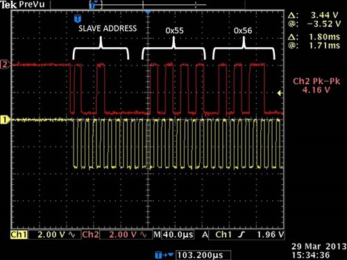
The waveforms of SDA and SCL shown on oscillator really bothers me. My devices are two G2553 EVMs.

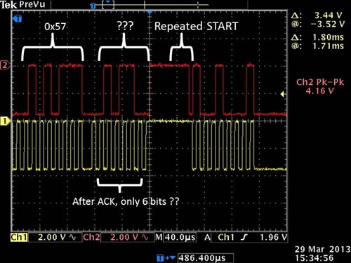
I printed the waveforms. The first time master transmits data to slave, 0x55, 0x56, 0x57, and after 0x57 comes with a only 6 bits something

It seems to be 0x58 but the code only transmits 3 bytes at a time. So what is that ?

After master TX (0x55, 0x56, 0x57), then slave TX (0x11, 0x12), and continue with master TX (0x5A, 0x5B, 0x5C), some bytes lost !?  

0x58 & 0x59 didn't show on the oscillator.  This also happen when slave TX again, 0x13 didn't appear but starts with 0x14 and 0x15.

 Could someone explain this or has the same question?         Thanks in advance! 


  • I don't know the code, but apparentlythe sending process is just interrupted mid-byte. Maybe lack of proper synchronization between the main thread and the ISR that does the transfer. The main code doesn't wait until data is sent completely.
    Just a guess.

  • Wow. That is a horrible example program that TI is giving out. I would dare to say that it was written by a college student except for the fact that there are comments in it.

    First, the ISR doesn't even check any interrupt register flags, it just assumes whether TX or RX is happening based on some global flags. It is difficult to wade through the ISR code because of poor indentation (every line is different regardless of which if/else it belongs to!!).

    My suggestion would be to find better code example if you can. Otherwise, try to restructure the code a little to follow what's going on.

    I'm attaching the file if anyone is interested in seeing it....

    3175.msp430g2xx3_uscib0_i2c_12.c
    /* --COPYRIGHT--,BSD_EX
     * Copyright (c) 2012, Texas Instruments Incorporated
     * All rights reserved.
     *
     * Redistribution and use in source and binary forms, with or without
     * modification, are permitted provided that the following conditions
     * are met:
     *
     * *  Redistributions of source code must retain the above copyright
     *    notice, this list of conditions and the following disclaimer.
     *
     * *  Redistributions in binary form must reproduce the above copyright
     *    notice, this list of conditions and the following disclaimer in the
     *    documentation and/or other materials provided with the distribution.
     *
     * *  Neither the name of Texas Instruments Incorporated nor the names of
     *    its contributors may be used to endorse or promote products derived
     *    from this software without specific prior written permission.
     *
     * THIS SOFTWARE IS PROVIDED BY THE COPYRIGHT HOLDERS AND CONTRIBUTORS "AS IS"
     * AND ANY EXPRESS OR IMPLIED WARRANTIES, INCLUDING, BUT NOT LIMITED TO,
     * THE IMPLIED WARRANTIES OF MERCHANTABILITY AND FITNESS FOR A PARTICULAR
     * PURPOSE ARE DISCLAIMED. IN NO EVENT SHALL THE COPYRIGHT OWNER OR
     * CONTRIBUTORS BE LIABLE FOR ANY DIRECT, INDIRECT, INCIDENTAL, SPECIAL,
     * EXEMPLARY, OR CONSEQUENTIAL DAMAGES (INCLUDING, BUT NOT LIMITED TO,
     * PROCUREMENT OF SUBSTITUTE GOODS OR SERVICES; LOSS OF USE, DATA, OR PROFITS;
     * OR BUSINESS INTERRUPTION) HOWEVER CAUSED AND ON ANY THEORY OF LIABILITY,
     * WHETHER IN CONTRACT, STRICT LIABILITY, OR TORT (INCLUDING NEGLIGENCE OR
     * OTHERWISE) ARISING IN ANY WAY OUT OF THE USE OF THIS SOFTWARE,
     * EVEN IF ADVISED OF THE POSSIBILITY OF SUCH DAMAGE.
     *
     *******************************************************************************
     * 
     *                       MSP430 CODE EXAMPLE DISCLAIMER
     *
     * MSP430 code examples are self-contained low-level programs that typically
     * demonstrate a single peripheral function or device feature in a highly
     * concise manner. For this the code may rely on the device's power-on default
     * register values and settings such as the clock configuration and care must
     * be taken when combining code from several examples to avoid potential side
     * effects. Also see www.ti.com/grace for a GUI- and www.ti.com/msp430ware
     * for an API functional library-approach to peripheral configuration.
     *
     * --/COPYRIGHT--*/
    //******************************************************************************
    //  MSP430G2xx3 Demo - USCI_B0 I2C Master TX/RX multiple bytes from MSP430 Slave
    //                     with a repeated start in between TX and RX operations.
    //
    //  Description: This demo connects two MSP430's via the I2C bus. The master
    //  transmits to the slave, then a repeated start is generated followed by a 
    //  receive operation. This is the master code. This code demonstrates how to 
    //  implement an I2C repeated start with the USCI module using the USCI_B0 TX 
    //  interrupt.
    //  ACLK = n/a, MCLK = SMCLK = BRCLK = default DCO = ~1.2MHz
    //
    //	***to be used with msp430x22x4_uscib0_i2c_13.c***
    //
    //                                /|\  /|\
    //               MSP430F24x      10k  10k     MSP430G2xx3
    //                   slave         |    |        master
    //             -----------------   |    |  -----------------
    //           -|XIN  P3.1/UCB0SDA|<-|---+->|P3.1/UCB0SDA  XIN|-
    //            |                 |  |      |                 |
    //           -|XOUT             |  |      |             XOUT|-
    //            |     P3.2/UCB0SCL|<-+----->|P3.2/UCB0SCL     |
    //            |                 |         |                 |
    //
    //  D. Dang
    //  Texas Instruments Inc.
    //  February 2011
    //  Built with CCS Version 4.2.0 and IAR Embedded Workbench Version: 5.10
    //******************************************************************************
    #include <msp430.h>
    
    #define NUM_BYTES_TX 3                         // How many bytes?
    #define NUM_BYTES_RX 2
    
    int RXByteCtr, RPT_Flag = 0;                // enables repeated start when 1
    volatile unsigned char RxBuffer[128];       // Allocate 128 byte of RAM
    unsigned char *PTxData;                     // Pointer to TX data
    unsigned char *PRxData;                     // Pointer to RX data
    unsigned char TXByteCtr, RX = 0;
    unsigned char MSData = 0x55;
    
    void Setup_TX(void);
    void Setup_RX(void);
    void Transmit(void);
    void Receive(void);
    
    int main(void)
    {
      WDTCTL = WDTPW + WDTHOLD;                 // Stop WDT
      P1SEL |= BIT6 + BIT7;                     // Assign I2C pins to USCI_B0
      P1SEL2|= BIT6 + BIT7;                     // Assign I2C pins to USCI_B0
      
      while(1){
        
      //Transmit process
      Setup_TX();
      RPT_Flag = 1;
      Transmit();
      while (UCB0CTL1 & UCTXSTP);             // Ensure stop condition got sent
      
      //Receive process
      Setup_RX();
      Receive();
      while (UCB0CTL1 & UCTXSTP);             // Ensure stop condition got sent
      }
    }
    
    //-------------------------------------------------------------------------------
    // The USCI_B0 data ISR is used to move received data from the I2C slave
    // to the MSP430 memory. It is structured such that it can be used to receive
    // any 2+ number of bytes by pre-loading RXByteCtr with the byte count.
    //-------------------------------------------------------------------------------
    #pragma vector = USCIAB0TX_VECTOR
    __interrupt void USCIAB0TX_ISR(void)
    {
      if(RX == 1){                              // Master Recieve?
      RXByteCtr--;                              // Decrement RX byte counter
      if (RXByteCtr)
      {
        *PRxData++ = UCB0RXBUF;                 // Move RX data to address PRxData
      }
      else
      {
        if(RPT_Flag == 0)
            UCB0CTL1 |= UCTXSTP;                // No Repeated Start: stop condition
          if(RPT_Flag == 1){                    // if Repeated Start: do nothing
            RPT_Flag = 0;
          }
        *PRxData = UCB0RXBUF;                   // Move final RX data to PRxData
        __bic_SR_register_on_exit(CPUOFF);      // Exit LPM0
      }}
      
      else{                                     // Master Transmit
          if (TXByteCtr)                        // Check TX byte counter
      {
        UCB0TXBUF = MSData++;                   // Load TX buffer
        TXByteCtr--;                            // Decrement TX byte counter
      }
      else
      {
        if(RPT_Flag == 1){
        RPT_Flag = 0;
        PTxData = &MSData;                      // TX array start address
        TXByteCtr = NUM_BYTES_TX;                  // Load TX byte counter
        __bic_SR_register_on_exit(CPUOFF);
        }
        else{
        UCB0CTL1 |= UCTXSTP;                    // I2C stop condition
        IFG2 &= ~UCB0TXIFG;                     // Clear USCI_B0 TX int flag
        __bic_SR_register_on_exit(CPUOFF);      // Exit LPM0
        }
      }
     }
      
    }
    
    void Setup_TX(void){
      _DINT();
      RX = 0;
      IE2 &= ~UCB0RXIE;  
      while (UCB0CTL1 & UCTXSTP);               // Ensure stop condition got sent// Disable RX interrupt
      UCB0CTL1 |= UCSWRST;                      // Enable SW reset
      UCB0CTL0 = UCMST + UCMODE_3 + UCSYNC;     // I2C Master, synchronous mode
      UCB0CTL1 = UCSSEL_2 + UCSWRST;            // Use SMCLK, keep SW reset
      UCB0BR0 = 12;                             // fSCL = SMCLK/12 = ~100kHz
      UCB0BR1 = 0;
      UCB0I2CSA = 0x48;                         // Slave Address is 048h
      UCB0CTL1 &= ~UCSWRST;                     // Clear SW reset, resume operation
      IE2 |= UCB0TXIE;                          // Enable TX interrupt
    }
    void Setup_RX(void){
      _DINT();
      RX = 1;
      IE2 &= ~UCB0TXIE;  
      UCB0CTL1 |= UCSWRST;                      // Enable SW reset
      UCB0CTL0 = UCMST + UCMODE_3 + UCSYNC;     // I2C Master, synchronous mode
      UCB0CTL1 = UCSSEL_2 + UCSWRST;            // Use SMCLK, keep SW reset
      UCB0BR0 = 12;                             // fSCL = SMCLK/12 = ~100kHz
      UCB0BR1 = 0;
      UCB0I2CSA = 0x48;                         // Slave Address is 048h
      UCB0CTL1 &= ~UCSWRST;                     // Clear SW reset, resume operation
      IE2 |= UCB0RXIE;                          // Enable RX interrupt
    }
    void Transmit(void){
        PTxData = &MSData;                      // TX array start address
        TXByteCtr = NUM_BYTES_TX;                  // Load TX byte counter
        while (UCB0CTL1 & UCTXSTP);             // Ensure stop condition got sent
        UCB0CTL1 |= UCTR + UCTXSTT;             // I2C TX, start condition
        __bis_SR_register(CPUOFF + GIE);        // Enter LPM0 w/ interrupts
    }
    void Receive(void){
        PRxData = (unsigned char *)RxBuffer;    // Start of RX buffer
        RXByteCtr = NUM_BYTES_RX-1;              // Load RX byte counter
        while (UCB0CTL1 & UCTXSTP);             // Ensure stop condition got sent
        UCB0CTL1 |= UCTXSTT;                    // I2C start condition
        __bis_SR_register(CPUOFF + GIE);        // Enter LPM0 w/ interrupts
    }


  • Brian Boorman said:
    Wow. That is a horrible example program that TI is giving out. I would dare to say that it was written by a college student except for the fact that there are comments in it.

    Yes, I was surprised to see that many comments on it. Even though these comments do not shed much light on the overall concept/strategy of the code, they at least tell clearly what is done in every step (but unfortunately not why it is done).

    Now if you read the header ocmments carefully, you'll see that the code is solely for demonstrating a repeated start in conjunciton with some other demo code on the attached slave. It is not meant to be a full-featured I2C implementation.

    My biggest complaint about the code is that is uses a flag to switch between repeated start and start/stop mode, so the code does more then jsu tdemonstrating a repeated start and this 'more' of funcitonality might cause some confusion is someone tries to understand the 'how'.

    A second look reveals that the code has a 2011 creation date, but the copyright notice has a 2012 date. So it was definitely touched since it was written. No idea whether jsut the copyright notice was added/replaced or other changes were made without adding a revision history.
    The messed-up indentation might be because of the habit (which I also have) of putting teh opening bracket right behind the if/do/while. It saves one line and lets you scroll much less on larger code.
    However, proper indentation is needed then. But maybe the code was also fed through an auto-formatting program later, which didn't cope well with those inlined brackets. Or tabstops have been translated into spaces. Since there is no general rule of how wide a tabstop is, and you don't usually see (nor care for) the width of tabstops in the editor as long as it looks right on your screen, the bad indentaiton is probably not the fault of the code writer.

    After all, I've really seen worse example codes.

  • Thank you all for the suggestions~

    If you are interested in the master and slave  codes, here they are

    2500.msp430g2xx3_uscib0_i2c_12.c
    //******************************************************************************
    //  MSP430G2xx3 Demo - USCI_B0 I2C Master TX/RX multiple bytes from MSP430 Slave
    //                     with a repeated start in between TX and RX operations.
    //
    //  Description: This demo connects two MSP430's via the I2C bus. The master
    //  transmits to the slave, then a repeated start is generated followed by a 
    //  receive operation. This is the master code. This code demonstrates how to 
    //  implement an I2C repeated start with the USCI module using the USCI_B0 TX 
    //  interrupt.
    //  ACLK = n/a, MCLK = SMCLK = BRCLK = default DCO = ~1.2MHz
    //
    //	***to be used with msp430x22x4_uscib0_i2c_13.c***
    //
    //                                /|\  /|\
    //               MSP430F24x      10k  10k     MSP430G2xx3
    //                   slave         |    |        master
    //             -----------------   |    |  -----------------
    //           -|XIN  P3.1/UCB0SDA|<-|---+->|P3.1/UCB0SDA  XIN|-
    //            |                 |  |      |                 |
    //           -|XOUT             |  |      |             XOUT|-
    //            |     P3.2/UCB0SCL|<-+----->|P3.2/UCB0SCL     |
    //            |                 |         |                 |
    //
    //  D. Dang
    //  Texas Instruments Inc.
    //  February 2011
    //  Built with CCS Version 4.2.0 and IAR Embedded Workbench Version: 5.10
    //******************************************************************************
    #include <msp430.h>
    
    #define NUM_BYTES_TX 3                         // How many bytes?
    #define NUM_BYTES_RX 2
    
    int RXByteCtr, RPT_Flag = 0;                // enables repeated start when 1
    volatile unsigned char RxBuffer[128];       // Allocate 128 byte of RAM
    unsigned char *PTxData;                     // Pointer to TX data
    unsigned char *PRxData;                     // Pointer to RX data
    unsigned char TXByteCtr, RX = 0;
    unsigned char MSData = 0x55;
    
    void Setup_TX(void);
    void Setup_RX(void);
    void Transmit(void);
    void Receive(void);
    
    int main(void)
    {
      WDTCTL = WDTPW + WDTHOLD;                 // Stop WDT
      P1SEL |= BIT6 + BIT7;                     // Assign I2C pins to USCI_B0
      P1SEL2|= BIT6 + BIT7;                     // Assign I2C pins to USCI_B0
      
      while(1){
        
      //Transmit process
      Setup_TX();
      RPT_Flag = 1;
      Transmit();
      while (UCB0CTL1 & UCTXSTP);             // Ensure stop condition got sent
      
      //Receive process
      Setup_RX();
      Receive();
      while (UCB0CTL1 & UCTXSTP);             // Ensure stop condition got sent
      }
    }
    
    //-------------------------------------------------------------------------------
    // The USCI_B0 data ISR is used to move received data from the I2C slave
    // to the MSP430 memory. It is structured such that it can be used to receive
    // any 2+ number of bytes by pre-loading RXByteCtr with the byte count.
    //-------------------------------------------------------------------------------
    #pragma vector = USCIAB0TX_VECTOR
    __interrupt void USCIAB0TX_ISR(void)
    {
      if(RX == 1){                              // Master Recieve?
    	  RXByteCtr--;                              // Decrement RX byte counter
    	  if(RXByteCtr)
    	  {
    		*PRxData++ = UCB0RXBUF;                 // Move RX data to address PRxData
    	  }
    	  else
    	  {
    		  if(RPT_Flag == 0)
    			UCB0CTL1 |= UCTXSTP;                // No Repeated Start: stop condition
    		  if(RPT_Flag == 1){                    // if Repeated Start: do nothing
    			RPT_Flag = 0;
    		  }
    		*PRxData = UCB0RXBUF;                   // Move final RX data to PRxData
    		__bic_SR_register_on_exit(CPUOFF);      // Exit LPM0
    	  }
      }
      
      else{                                     // Master Transmit
          if (TXByteCtr)                        // Check TX byte counter
    	  {
    		UCB0TXBUF = MSData++;                   // Load TX buffer
    		TXByteCtr--;                            // Decrement TX byte counter
    	  }
    	  else
    	  {
    				if(RPT_Flag == 1){
    				RPT_Flag = 0;
    				PTxData = &MSData;                      // TX array start address
    				TXByteCtr = NUM_BYTES_TX;                  // Load TX byte counter
    				__bic_SR_register_on_exit(CPUOFF);
    				}
    				else{
    				UCB0CTL1 |= UCTXSTP;                    // I2C stop condition
    				IFG2 &= ~UCB0TXIFG;                     // Clear USCI_B0 TX int flag
    				__bic_SR_register_on_exit(CPUOFF);      // Exit LPM0
    				}
    	  }
      }
      
    }
    
    void Setup_TX(void){
      _DINT();                                  // _disable_interrupts()
      RX = 0;
      IE2 &= ~UCB0RXIE;  
      while (UCB0CTL1 & UCTXSTP);               // Ensure stop condition got sent// Disable RX interrupt
      UCB0CTL1 |= UCSWRST;                      // Enable SW reset
      UCB0CTL0 = UCMST + UCMODE_3 + UCSYNC;     // I2C Master, synchronous mode
      UCB0CTL1 = UCSSEL_2 + UCSWRST;            // Use SMCLK, keep SW reset
      UCB0BR0 = 12;                             // fSCL = SMCLK/12 = ~100kHz
      UCB0BR1 = 0;
      UCB0I2CSA = 0x48;                         // Slave Address is 048h
      UCB0CTL1 &= ~UCSWRST;                     // Clear SW reset, resume operation
      IE2 |= UCB0TXIE;                          // Enable TX interrupt
    }
    void Setup_RX(void){
      _DINT();
      RX = 1;
      IE2 &= ~UCB0TXIE;  
      UCB0CTL1 |= UCSWRST;                      // Enable SW reset
      UCB0CTL0 = UCMST + UCMODE_3 + UCSYNC;     // I2C Master, synchronous mode
      UCB0CTL1 = UCSSEL_2 + UCSWRST;            // Use SMCLK, keep SW reset
      UCB0BR0 = 12;                             // fSCL = SMCLK/12 = ~100kHz
      UCB0BR1 = 0;
      UCB0I2CSA = 0x48;                         // Slave Address is 048h
      UCB0CTL1 &= ~UCSWRST;                     // Clear SW reset, resume operation
      IE2 |= UCB0RXIE;                          // Enable RX interrupt
    }
    void Transmit(void){
        PTxData = &MSData;                      // TX array start address
        TXByteCtr = NUM_BYTES_TX;               // Load TX byte counter
        while (UCB0CTL1 & UCTXSTP);             // Ensure stop condition got sent
        UCB0CTL1 |= UCTR + UCTXSTT;             // I2C TX, start condition
        __bis_SR_register(CPUOFF + GIE);        // Enter LPM0 w/ interrupts
    }
    void Receive(void){
        PRxData = (unsigned char *)RxBuffer;    // Start of RX buffer
        RXByteCtr = NUM_BYTES_RX-1;             // Load RX byte counter
        while (UCB0CTL1 & UCTXSTP);             // Ensure stop condition got sent
        UCB0CTL1 |= UCTXSTT;                    // I2C start condition
        __bis_SR_register(CPUOFF + GIE);        // Enter LPM0 w/ interrupts
    }
    
    
    1145.msp430g2xx3_uscib0_i2c_13.c
    //******************************************************************************
    //  MSP430x22x4 Demo - USCI_B0 I2C Slave RX/TX multiple bytes to MSP430 Master
    //
    //  Description: This demo connects two MSP430's via the I2C bus. The slave
    //  recieves then transmits to the master. This is the slave code. The interrupt 
    //  driven data transmission is demonstrated using the USCI_B0 TX interrupt.
    //  ACLK = n/a, MCLK = SMCLK = default DCO = ~1.045Mhz
    //
    //	***to be used with msp430x22x4_uscib0_i2c_12.c***
    //
    //                                /|\  /|\
    //               MSP430G2xx3       10k  10k     MSP430G2xx3
    //                   slave         |    |        master
    //             -----------------   |    |  -----------------
    //           -|XIN  P3.1/UCB0SDA|<-|---+->|P3.1/UCB0SDA  XIN|-
    //            |                 |  |      |                 |
    //           -|XOUT             |  |      |             XOUT|-
    //            |     P3.2/UCB0SCL|<-+----->|P3.2/UCB0SCL     |
    //            |                 |         |                 |
    //
    //  D. Dang
    //  Texas Instruments Inc.
    //  February 2011
    //  Built with CCS Version 4.2.0 and IAR Embedded Workbench Version: 5.10
    //******************************************************************************
    #include <msp430.h>
    
    
    #define NUM_BYTES  2                       // How many bytes?
    //**** Please note this value needs to be the same as NUM_BYTES_RX in the
    //     associated master code. This definition lets the slave know when to
    //     switch from RX interrupt sources to TX interrupt sources. This is 
    //     important since the interrupt vectors are shared by TX and RX flags.
    
    unsigned char *PTxData;                     // Pointer to TX data
    unsigned char *PRxData;                     // Pointer to RX data
    volatile unsigned char RxBuffer[128];       // Allocate 128 byte of RAM
    char SLV_Data = 0x11;
    volatile unsigned char TXByteCtr, RXByteCtr, RX = 0;
    volatile unsigned char RxBuffer[128];       // Allocate 128 byte of RAM
    
    
    void USCI_SLAVE_SETUP(void);
    void Setup_RX(void);
    void Receive(void);
    
    int main(void)
    {
      WDTCTL = WDTPW + WDTHOLD;                 // Stop WDT
     
      while(1){
      USCI_SLAVE_SETUP();
      }
    }
    
    //------------------------------------------------------------------------------
    // The USCI_B0 data ISR is used to move data from MSP430 memory to the
    // I2C master. PTxData points to the next byte to be transmitted, and TXByteCtr
    // keeps track of the number of bytes transmitted.
    //------------------------------------------------------------------------------
    #pragma vector = USCIAB0TX_VECTOR
    __interrupt void USCIAB0TX_ISR(void)
    {
      if(RX == 0)
      { UCB0TXBUF = SLV_Data++;      // Transmit data at address PTxData
      	TXByteCtr++;                              // Increment TX byte counter
      }  
      if(RX == 1)
      {	*PRxData++ = UCB0RXBUF;       // Move RX data to address PRxData
      	RXByteCtr++;                              // Increment RX byte count
      	if(RXByteCtr >= NUM_BYTES){        //>=       // Received enough bytes to switch
    	  RX = 0;                                   // to TX?
    	  IE2 &= ~UCB0RXIE;
    	  IE2 |= UCB0TXIE;
    	  RXByteCtr = 0;
    	}
      }
    }
    
    //------------------------------------------------------------------------------
    // The USCI_B0 state ISR is used to wake up the CPU from LPM0 in order to do
    // processing in the main program after data has been transmitted. LPM0 is
    // only exit in case of a (re-)start or stop condition when actual data
    // was transmitted.
    //------------------------------------------------------------------------------
    #pragma vector = USCIAB0RX_VECTOR
    __interrupt void USCIAB0RX_ISR(void)
    { 
      if(RX == 0)
      { UCB0STAT &= ~(UCSTPIFG + UCSTTIFG);       // Clear interrupt flags
      	if (TXByteCtr)                            // Check TX byte counter
          __bic_SR_register_on_exit(CPUOFF);       // Exit LPM0 if data was
      }                                           // transmitted
      if(RX == 1)
      {
    	UCB0STAT &= ~(UCSTPIFG + UCSTTIFG);       // Clear interrupt flags
      }
    }
    void Setup_RX(void){
      _DINT();
      RX = 1;
      IE2 &= ~UCB0TXIE;                         // Disable TX interrupt
      UCB0CTL1 |= UCSWRST;                      // Enable SW reset
      UCB0CTL0 = UCMODE_3 + UCSYNC;             // I2C Slave, synchronous mode
      UCB0I2COA = 0x48;                         // Own Address is 048h
      UCB0CTL1 &= ~UCSWRST;                     // Clear SW reset, resume operation
      UCB0I2CIE |= UCSTPIE + UCSTTIE;           // Enable STT and STP interrupt
      IE2 |= UCB0RXIE;                          // Enable RX interrupt
      
    }
    
    void Receive(void){
        PRxData = (unsigned char *)RxBuffer;    // Start of RX buffer
        RXByteCtr = 0;                          // Clear RX byte count
        TXByteCtr = 0;
        __bis_SR_register(CPUOFF + GIE);        // Enter LPM0 w/ interrupts
                                                // Remain in LPM0 until master
                                                // finishes TX
    }
    void USCI_SLAVE_SETUP(void){
      P1SEL |= BIT6 + BIT7;                     // Assign I2C pins to USCI_B0
      P1SEL2|= BIT6 + BIT7;                     // Assign I2C pins to USCI_B0
      Setup_RX();
      Receive();
    }
    

    I've deleted the copyright parts from the original example codes for convenience. My devices are two MSP430 LaunchPad with g2553 so the pins for SDA and SCL are 1.7 & 1.6 which are different with the header comments.

    And Jens-Michael you said, "My biggest complaint about the code is that is uses a flag to switch between repeated start and start/stop mode, so the code does more then just demonstrating a repeated start and this 'more' of funcitonality might cause some confusion is someone tries to understand the 'how'. "

    Did you mean that I should try modify the code from this flag? Or any other ideas after seeing both master & slave codes? By the way, I tried both observing the waveforms and watching registers' changes in CCS to debug. The results were different which were another confusion. But since you all considered the example codes are bad and messy,  maybe I should not count on it.

  • Liwen Chang said:
    Did you mean that I should try modify the code from this flag?

    No, this comment was regarding th eusage of a multi-funcitonal code with runtime configuration switches as a good demo for demonstrating just one specific operationg mode. There's some overhead that isn't needed for the (explicitely stated) demonstration purpose. Which rather leads to confusion than to clarification on how to do something.

    Liwen Chang said:
    But since you all considered the example codes are bad and messy,  maybe I should not count on it.

    The usually do what they are intended to do. The complaints are against their educational value, not the functional one.

    Liwen Chang said:
    watching registers' changes in CCS to debug.

    Watchign register changes in the debugger isn't a good idea. Data transfers are usually realtime, and stopping mid-code so the debugger can update a register, interferes with the ongoing transfer.
    Also, teh debugger can only notice a register change by either reading the register (whcih isn't a good idea since constant data fetching would slow down the MSP to a virtual stop) or if there is a bus write  on this address (which can trigger a data access breakpoint in the MSP hardware but onyl happens when the CPU writes to the register, not if it changes by itself).
    So I don't think you're seeing the real story in the debugger.
    Letting the CPU copy the register content to a port and read the port pins by a logic analyzer would be not intrusive and give you a real 'real-time' view of what's going on.

    Sometimes the debugger is a bugger and you're better off without it. :)

**Attention** This is a public forum