This thread has been locked.

If you have a related question, please click the "Ask a related question" button in the top right corner. The newly created question will be automatically linked to this question.

Communicate through uart ports(TXD/RXD) with a single wire.Is this possible in MSP430?

Other Parts Discussed in Thread: MSP430F149

I'm using msp430F149 's uart ports (ie TXD and RXD) to communicate with another MCU device. Due to some specific hardware consideration of my target device, I have to use a single wire to make a duplex channel to that MCU device.  I've been working on the solution for a week, now I'm doubt if it is even possible to do that.

And I have tried with the following idea, but all the trials have been failed so far :

Initialize and enable UART module.(TX module enabled and RX module disabled)

 Send 8 bytes , one byte each time in the TX interrupt service routine. Maintain tx_counter to keep track of the index of the sending byte, and set it to zero before it tries to send 9th byte and disable TX module & enable RX module. By the protocol , the target device will reply a hand shake (8 bytes) , so likewise in the RX interrupt service routine I disable RX module & enable TX module in the 9th iteration.

Roughly speaking I intended to use a single wire for duplex uart communication in this way. 

  • Did you try using the 'Search' facility:

    http://e2e.ti.com/support/microcontrollers/stellaris_arm/f/471/t/251417.aspx

    http://e2e.ti.com/support/microcontrollers/stellaris_arm/f/471/t/253314.aspx

    xiao bing said:
    I have tried with the following idea, but all the trials have been failed so far :

    In what way(s), exactly, did they "fail"?

    What have you done to determine the cause(s) of those failures?

    Theres a number of steps in your procedure - how far does it get through them?

    xiao bing said:

    Roughly speaking I intended to use a single wire for duplex uart communication in this way. 

    This is known as "half-duplex"

  • xiao bing said:
    . Due to some specific hardware consideration of my target device, I have to use a single wire to make a duplex channel to that MCU device.

    You always need at least two wires for any kind of electrical communication. Electrons hesitate to leave if they don't see a way back. An exception is if you push them into an antenna, where they cry out loud that the electrons in all other antennae around get a panic attack and run into the receiver.

    So I hope you already considered at least a GND return wire in your concept, in addition to the data wire.

    Now how to communicate through 'one wire'? There are several 1-wire solutions already on the market.

    One way would indeed be what you tried with your UART approach. One device is the master and polls the answer form the slave. TX is set to module while sending, and switched to GPIO input when done. RX is connecte dot the same wire and switched to GPIO when not expecting an answer. THis is similar to RS-485, except that RS-485 uses a two wire differential line (but doesn't need a GND line as it is a current loop)

    Another possible approach is to combine I2C and UART. The signal wire is pulled up to VCC by a resistor and the sender only pulls it down. Instead of using the clock signal of the I2C bus (and its addressing method), high and low are interpreted jsut like an UART does: start bit, data bits, stop bit at a known baudrate. The only thing to add is that one side may only speak when the other is listening. So some sort of handshake or collision detection needs to be implemented (same problem as with RS-485). One way is a master/slave polling mechanism, another one is a token ring mechanism or  a timeslot approach. The advantage here is that there can be multiple slaves (or equal peers) and a collision won't drive outputs against each other. Drawback is that you can't use the hardware UART for the bitstream generation, because the UART only supports open-collector output in I2C mode, not in UART mode. You'll have to do it in GPIO.

    BTW: to simulate the open collector port pin that only pulls low but not high, you'll have to toggle the PxDIR bit not the PxOUT bit (which remains low all the time) to switch between active low output and passive input, pulled high by the pullup resistor.

  • Jens-Michael Gross said:
    So I hope you already considered at least a GND return wire in your concept, in addition to the data wire.

    Well, I have a GND wire. And I have tried the first approach before I post here.Probably I have implemented that in the wrong way.So how I switch RX/TX between GPIO and uart mode in msp430F149? By simply configure PxSEL register? ........

    Anyway I will try that again after I solve the following  problem (With two wires for TX and RX.... yep and one wire for GND ).

     In the session  between master and slave it always start with a request R(an fixed 8 bytes packet) and end with a handshake H(fixed 8 bytes) from the slave. Both R and H have been labeled a head(say 0xAA) in the 1st byte and taged a tail (0x0D) in 8th byte. And all the remaining 6 bytes in R and H contains the data to be processed by the Slave and  Master respectively. Then I buffered H in the master side's programe.

    Maybe for the uart mode or some other reason I don't know, when I debuged my programe of the master side, the packet H I recv from the salve arrived in the wrong order some time. So I implemented the following posudocode for the master side :

    ------------------------------------------------------------------------------------------------------------------------------------

    enter the recv ISR, buffered the H in buf.

    while( !(buf[0] == 0xAA && but[7] == 0x0D) ) {  //heah == 0xAA and tail == 0x0D

        send packet R; // 8 bytes send in ISR, one byte each time, same way as my previous post

        delay 10 ms;  // I think this will give the master recv ISR sufficient time.

    }

    Master handle the other 6 bytes;

    ----------------------------------------------------------------------------------------------------------------------------------

     The H has to be reached in order by my logic and I checked that in the watch window in IAR.And the programe worked for the first time in my board. With uart ports connected to PC, I observed everything worked the way I expected.I was about to enjoy a happy morning when I first debuged this in simulator. Then it goes evil when I rerun it. The master seemed crashed and sended R wildly to the slave. So maybe I forced the master to enter a wild loop? Then I limit the loop to be excuted at most 5 five times, but still it sended the packet rapidly.

    So I can not write the code this way in MCU and this is totally a wrong way to do?

    [English is not my native language, so hope I have made my question clear.]

  • Andy Neil said:

    This is known as "half-duplex"

    So one side send data while the other stand down and wait is "half-duplex"?

    Thanks for your correction.  :)

  • You might want to take a look at this paper about parsing messages from a "stream" of data:

    http://www.visualgps.net/WhitePapers/NMEAParser/NMEAParser.html

    It's specifically looking at NMEA sentences (GPS data) - but the principles are generally applicable...

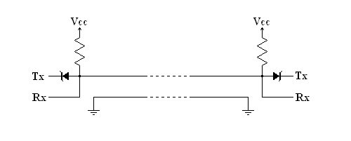
  • I have a crude hardware interface circuit for half-duplex One-Wire UART to UART connection as shown here.  

    Both Tx and Rx are assumed to be active low. If Tx is from an open collector or open drain, the diode is not needed. This interface is prone to ground noise and RF interference.  It can also be very slow due the stray capacitance of the wire.

    A fairly robust software protocol is as follows:

    Both sides are normally in a watch-request-state (see below for details of how a request is made).

    If a request from the other side is detected, the detecting side enters a receive-data-state. It stays in this state until there is no more data from the other side.  That condition is detected by a prearranged Rx timeout or by a prearranged special EOT byte appended to the end of data bytes. Either way, the side exits the receive-data-state and goes back to watch-request-state.

    While both sides are in the watch-request-state, if either side wants to transmit data, it has to (a) make sure the other side is not sending a request, (b) send a 2-byte request of its own, and (c) receive the loop-back echo of that 2-byte request.  I suggest that one side uses 0xFF, 0xFF while the other side uses 0xFE, 0xFF as the said 2-byte request.

    If the correct loop-back bytes are received, it indicates that there was no collision on the One-Wire interface and the side that makes the request goes into transmit-data-state. When all data bytes are transmitted, it uses either one of the aforementioned methods to end this transmit-data-state and goes back to watch-request-state.

  • I forgot to mention what to do when making a request and (c) resulted in incorrect loop-back echo bytes. In such a case, the code should (i) go back to watch-request-state, (ii) wait for a random period of time, and (iii) try to make the request again.

    This procedure is used to resolve collisions (that is, when both sides try to request at about the same time).

  • xiao bing said:
    I intended to use a single wire for duplex uart communication

    Well it is quite possible to implement a full duplex communication on a single pair of wires, every analog phone is capable of this.

    To implement this feature phones use a hybrid transformer. 

    A digital version of a hybrid transformer can be implemented with couple of comparators and handfull of resistors.

    Peter

  • old_cow_yellow said:
    If a request from the other side is detected, the detecting side enters a receive-data-state. It stays in this state until there is no more data from the other side.  That condition is detected by a prearranged Rx timeout or by a prearranged special EOT byte appended to the end of data bytes. Either way, the side exits the receive-data-state and goes back to watch-request-state.

    I have tried your solution. The first trial goes like this:

    -------------------------------------------------------------------------------

    Master side send R;

    while(!(head == Start_Byte && tail == EOT)); //keeps waiting untill a complete packet buffered into memory.

    -------------------------------------------------------------------------------

    It's working on the first trial. Then the msp430 MCU did not respond to the key pad input any more, looks like it's freezed. Then I reset my board, same thing happen again.

    The second trial is a happy one.(At least untill now......). Posudocode goes like the following:

    -------------------------------------------------------------------------------

    while(1)
    {
    if(!(head == Start_Byte && tail == EOT))
    {
    Master send request;
    //Maybe some dealy; // I comment this out, it looks still working to me.
    continue;
    }
    else break;
    }


    -------------------------------------------------------------------------------

    old_cow_yellow said:
    While both sides are in the watch-request-state, if either side wants to transmit data, it has to (a) make sure the other side is not sending a request, (b) send a 2-byte request of its own, and (c) receive the loop-back echo of that 2-byte request.  I suggest that one side uses 0xFF, 0xFF while the other side uses 0xFE, 0xFF as the said 2-byte request.

    Unfortunately I can not modify the slave side's protocol now.So I have to test my code again and again....

    And thanks for your post. It's really helpful.

    :)

  • Andy Neil said:
    It's specifically looking at NMEA sentences (GPS data) - but the principles are generally applicable...

    I have read the paper. Well I am sort of new to programming,NMEA is complicated for me. However this will be a good guide to deal with more complex task in the future.

    Thanks. :)

  • old_cow_yellow said:
    I have a crude hardware interface circuit for half-duplex One-Wire UART to UART connection as shown here.  

    Well, another question about the circuit. For now I use a same msp430 MCU to simulate my target device(slave) which uses 3.3V power supply.

    And my actual target device's MCU uses 5V power supply. Can I connect them directly ? Will anything goes wrong during the uart data trans/recv? 

  • xiao bing said:
    I am sort of new to programming

    Then I would strongly suggest that you spend some time getting a really solid understanding of how serial comms works over a "normal" 2-wire connection before complicating the issue with the single-wire thing!

    You can still implement the same protocol over 2 wires - once that's working, then move onto the single-wire connection.

    xiao bing said:
    NMEA is complicated for me

    You don't need to go into all the details of NMEA - simply observe the way that the code looks for specific sequences in the data stream to mark the start and end of a "message" (or "packet")...


  • old_cow_yellow said:
    I have a crude hardware interface circuit for half-duplex One-Wire UART to UART connection as shown here.  

    Looks quite much like I2C :) (except for the additional diode voltage).

    xiao bing said:
    For now I use a same msp430 MCU to simulate my target device(slave) which uses 3.3V power supply.
    And my actual target device's MCU uses 5V power supply. Can I connect them directly ?

    If the slave has real TTL compatible inputs, it should be fine to pull the line up to 3.3V when using OCYs circuit. This should be sufficient for a TTL input to be detected as high, even if the other peer is run on 5V. It never outputs 5V to the bus (the diode will prevent this).

    xiao bing said:
    So one side send data while the other stand down and wait is "half-duplex"?

    Not exactly. half-duplex is when one side has to stand down and wait while the other side talks. :)
    There are different approaches how this is accomplished: On some systems, one is master, and the slave only talks when asked by the master. On other systems, each side talsk at a certain timeslot. And other implementations simply detect when more than one is talking, then both back-up and wait for a random time and start over. Sooner or later, one will detect that the other has already started talking and remain silent. This way it was done on BNC ethernet or on 10BaseT HUBs.

    Imagine what happens when a large room full of Sun workstations with no local disk and not much ram try to boot (and swap) at the same time through one single ethernet cable from the same server when the power is switched on in the morning with the main switch.
    I'll tell you: nothing. If you don't go and switch all off but one, and then one by one on again after the previous has finished booting, then the whole set of workstations will waste all the day colliding with their network traffic :) (whoever andministered this setup should have been fired instantly)
    That's the way I learned about half-duplex at university)

  • Jens-Michael Gross said:
    One way would indeed be what you tried with your UART approach. One device is the master and polls the answer form the slave. TX is set to module while sending, and switched to GPIO input when done. RX is connecte dot the same wire and switched to GPIO when not expecting an answer.

    In the uart_init(), I set TXD(P3.4) to uart and RXD(P3.5 for msp430f149), enable TX module and disable RX module.

    The master send 8 bytes request in the ISR, one byte each time. The code for TX_ISR looks like the following:

    -----------------------------------------------------------------------------------------------------------------------------------------------

    #pragma vector = UART0TX_VECTOR
    __interrupt void UART0_TX()  {
    if(Bytes_send_cnt-- > 0)  {
    U0TXBUF = TX_BUF[TxIndex];
    if(++TxIndex >= 8)  {
    TxIndex = 0;
    }
    }

    else

    {
    uchar i;
    for(i = 150; i > 0; i--);  // Looks like I have to add some delay here, otherwise the TXD cannot send the 8th byte correctly.

    P3SEL &= ~U0TXD;
    P3DIR &= ~U0TXD;

    IE1 &= ~UTXIE0;
    IFG1 &= ~UTXIFG0;
    ME1 &= ~UTXE0;
    Bytes_send_cnt = 8;

    P3SEL |= U0RXD; // #define U0RXD 0x20
    ME1 |= URXE0;
    IE1 |= URXIE0;
    }//disable TX @9th interation
    }

    ---------------------------------------------------------------------------------------------------------------------------------------

    And for RX_ISR:

    ---------------------------------------------------------------------------------------------------------------------------------------

    #pragma vector = UART0RX_VECTOR
    __interrupt void UART0_RX(){
    if(Bytes_recv_cnt-- > 0)  {
    RX_BUF[RxIndex] = U0RXBUF;
    if(++RxIndex >= 8){
    RxIndex = 0;

    IE1 &= ~URXIE0; IFG1 &= ~URXIFG0; ME1 &= ~URXE0;
    Bytes_recv_cnt = 8;
    P3SEL &= ~U0RXD; P3DIR |= U0RXD; 
     }
    }

    else

    {
      // This part will never be excuted.  There's no "9th byte" for master. 

    }
     
    }

    ----------------------------------------------------------------------------------------------------------------------------------

    In main(), the send_request() is triggered by key button. When I connect the TXD and RXD and then test the above code, the request bytes seemed trapped unless I disconnect them.

    ------------------------------------------------------------------------------------------------------------------------------------

    Updated Apr 29 2013    08:44 PM CST008

    For people who might as well working on this solution. Just follow the previous posted by  , one wire uart communication can be done in this way.


  • xiao bing said:
    the request bytes seemed trapped unless I disconnect them.

    Please explain what you mean by that!

    Again, have you tried this on a "normal" 2-wire connection? There's no point adding the complication of single-wire before you've even got the basic serial comms working!

  • Andy Neil said:
    Please explain what you mean by that!

    send_request() is supposed to be called in my programm when the button is pressed.

    On the master side , when RXD and TXD are connected,  the keypad input did not triggered the send_request() untill I disconnect them. 

    Andy Neil said:
    Again, have you tried this on a "normal" 2-wire connection? There's no point adding the complication of single-wire before you've even got the basic serial comms working!

    It's working for  "normal" 2-wire connection. The master send request and slave reply, and I checked that in debugger. 

  • Jens-Michael Gross said:
    One way would indeed be what you tried with your UART approach. One device is the master and polls the answer form the slave. TX is set to module while sending, and switched to GPIO input when done. RX is connecte dot the same wire and switched to GPIO when not expecting an answer. THis is similar to RS-485, except that RS-485 uses a two wire differential line (but doesn't need a GND line as it is a current loop)

    Okay, the problem has been soleved. Single wire can be achieved in this way for msp430.

**Attention** This is a public forum