This thread has been locked.

If you have a related question, please click the "Ask a related question" button in the top right corner. The newly created question will be automatically linked to this question.

Problems with programming custom made PCB - Spy By wire

Other Parts Discussed in Thread: MSP430F5507

Hi everyone! 

I have just received my PCB but I am having problems programming my MSP430f5507 MCU. I have a MSP-FET430UIF debugger and I use CCS v5 for the coding and I ahve tried using CCS to debug but also the FET-PRO430 programming software. Neither of these works and I cant program my MSP430f5507.

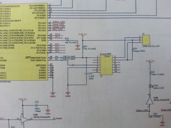
Below is a picture of the schematic connections of the JTAG interface. I use the 2-wire spy-by-wire connection but I cannot upload code into my MSP430f5507. The firmware of the FET debugger is 3.02.05.004. The card powers up like it should but I just cant initialize JTAG communication with my MSP. Can someone help me pls? The J1 connector is simply so I can choose if the processor should be powered from the battery or the debugger.

/Mikael  


  • MSP430F550x can be programmed without any tool or glue logic, by USB BSL (using just PC/uC USB connection), but unfortunately you didn't apply USB part on your board. Don't see what is with connections on other side of chip. AFAIK MSP430F5xx have internal RESET pullup resistor, so basically there is no need 47K on board. You can temporary remove R4/R5 resistors and connect 2 wires (TEST/RESET), directly from programing tool to TEST/RESET lines on chip (at R4/R5 position). Also you need ground line connection with programmer. If this fail, tray to play with cap on RESET pin. I hope that there is no problem with chip supply (AVCC/DVCC).

  • Thank you for reply! The programmer and debugger actually works well now for use in both Code Composer Studio and Lite FET-PRO430. 

    /Mikael

**Attention** This is a public forum