Other Parts Discussed in Thread: MSP430F5438A, MSP430F149
Hello,
This thread has been locked.
If you have a related question, please click the "Ask a related question" button in the top right corner. The newly created question will be automatically linked to this question.
Other Parts Discussed in Thread: MSP430F5438A, MSP430F149
Hello,
What are the pink and purple lines in your scope shot?
Maybe you should post your complete code, not just the few init lines.
Nevertheless, 00010111 isn't what I would read from the two pictures.
The RX waveform is (111)010001011101(111)
Sicne the start bit is always a 0 and the stop bit a 1 and the lenght is 10 bit, this waveform won't match the 00010111 pattern you mentioned.
For LSB first, the resulting 10 bit pattern pattern should be 0111010001 or for MSB first it would be 0000101111. (you see, after the start bit, your test byte has either 3 '1' bits or 3 '0' bits, depending on whcih side first, but never a signle '1' bit.)
It seems that you have inverted polarity and also the 'idle' level doesn't match the 'inactive' level, giving you inverted bits and a bogus start bit when the UART goes active. Are you doing RS485 or something liek that? Where are you connected to, and how?
Hello Jens-Michael,
First of all, thank you for taking the time to answer my question.
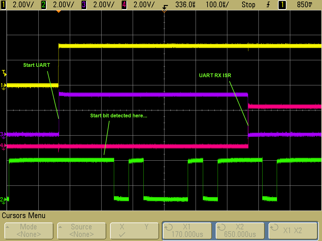
The purple line is a DIO which is toggled when the UART is started and toggled for each byte received (it is for debug on the oscilloscope)
The pink line is toggled whenever a byte is received with an error (it is also for the oscilloscope).
The yellow line is raised when I start a new 10-bytes sequence (it is the trigger for the oscilloscope)
The green line is the RX input of the UART of the MSP430F5438A
I think I haven't explained well enough the sequence.
1) Once we start a new 10-bytes sequence, the rx line is idle (green line at high)
2) I start the UART
3) The UART wait for the start bit (low)
4) The UART receives 8 bits
5) The UART receives the stop bit (high)
6) The UART receives the start bit (low) of the next byte
7) And so on for 10 consecutive bytes
8) When I've received the 10 bytes, I stop the UART
9) 500 ms later, I start another sequence, etc.
I don't understand how you decode the waveform, I agree with you that the RX waveform is (111)010001011101(111) and that my decoding was wrong but I don't understand how you do, I would do like that :
(111)010001011101(111)
The first three bits at 1 are the line in idle state.
The next bit at 0 is the start bit, then the next 8 bits are the data bits, the next bit at 1 is the stop bit, the next bit at 0 is the start bit of the next byte etc.
So in this case the pattern is 10001011 (you were right, I was wrong in my first post on picture 1).
The problem is that some time, at the start of a new sequence, the start bit is detected before it really happens which shifts all the bits and I don't understand why the UART would detect any start condition before this first start bit. We can see on the second picture that the RX ISR is raised one bit too early and that the start bit is considered as a data bit so the sequence is (using same colors as above) :
(111)010001011101(111)
So in this case the pattern is 01000101 which is wrong.
What you mean by : "it seems that you have inverted polarity and also the 'idle' level doesn't match the 'inactive' level"? The idle level is high which is the right way to do as far as I know. The device we are connected to is a proprietary device of our company and it is working fine with an MSP430F149.
For the code, the only other code that makes sens to post is the UartEnable code :
UCA0CTL1 |= UCSWRST;
// enable USART1
UCA0CTL1 &= ~UCSWRST;
// enable UART1 interrupt
UCA0IE |= UCRXIE;
And the UartDisable code :
// disable UART1 RX interrupt
UCA0IE &= ~UCRXIE;
// reset USART1 before configuring
UCA0CTL1 |= UCSWRST;
// enable USART1
UCA0CTL1 &= ~UCSWRST;
Best regards,
T.
I was taking your initial information of the data pattern as a fact (I mean, you should know what you are expecting to receive when doing tests). Assuming a problem with polarity etc was the only way to match the "known" bit pattern with the observed signal.Thierry said:What you mean by : "it seems that you have inverted polarity[...]
Yes and no. Yes, the itnerutp is raised too early, btu that doesn't mean that the start bit is taken as data bit. It may also mean that your baudrate is off or unstable (how do you generate the clock? Maybe there is Jitter by the FLL?).Thierry said:We can see on the second picture that the RX ISR is raised one bit too early and that the start bit is considered as a data bit so the sequence is
It is next to impossible that the MSP will start receiving a byte when there is no low-going edge. It will even suppress short glitches on the signal line.
What is the baudrate you want to achieve? If I read the scope shoot right, then the whole byte (10 bit) has a length of ~480µs. This gives a baudrate of ~20800Bd. Strange. With a divider of 1080, this means your clock source is around 22.5MHz? Sounds unusual too. (I'm calculating this based on the '100µs/' writing on the scope shoot)
I'd really like to see the clock system setup too. (the port pin configuration seems to be okay or else you wouldn't get any interrupts).Thierry said:For the code, the only other code that makes sens to post is the UartEnable code :
Hello Jens-Michael,
Thank you for your remarks. I will have a look at the clock setup because it seems to be the most probable source of errors.
As a clock I'm using an external XT2 oscillator at 25Mhz, the baudrate I want to achieve is 21187.5 bps (yes it's weird but it's the baudrate of our company device). The 1180 divider seems to be OK : 25000000 / 1180 = 21186.4 bps.
I will have a look at this next week.
Best regards,
Thierry
Hello Jean-Michael,
I went back to this problem today and I noticed something related with the clock (UCBCLK is sourced by SMCLK, I keep the same baudrate in both cases below):
1) If I set SMCLK = XT2 at 25Mhz, the problem occurs in about 13% of the byte sequences.
2) If I set SMCLK = XT2 / 2 at 12.5Mhz, the problem occurs in about 0.3% of the byte sequences.
It seems that there are some max limit for SMCLK frequency when sourcing UCBCLK but it's not very clear.
Best regards,
Thierry
THis is strange. Normally, teh clock speed (as long as in the allowed range) shouldn't make a difference. It is of cours epossible that if the baudrate is too high, your CPU code cannot catch up and may cause glitches due to racing conditions.
Well; i don't know your code.
A possible reason for problems is a small baudrate divider (high baudrate) in conjunction with a clock jitter and a bad baudrate divider setting.
If you use the DCO for clock, with FLL, the DCO clock speed will not only jitter up to 12% on each clock pulse, but may also change in average (over 32 clock pulses) once every 1/32768 s (assuming a 32768Hz reference for the FLL).
This causes a small shift in the baudrate. If the baudrate settings (especially the modulation part) is already shakey, this may cause the receiver to assume the bits it sees to be shorter than they really are, getting the last bit too early.
Lowering the clock speed of course also increases the timing window in which the bits are detected properly.
Note that the USCI re-synchronizes to the incoming data on the next cluck pulse after a start bit edge - but doesn't re-synchronize on a bit-level change mid-byte.
This is even stranger because I'm sourcing SMCLK with XT2 which is very stable à 25Mhz (I'v controlled SMCLK with the oscilloscope on P11 output) and my bitrate is quite low so the divider is big and almost round. Thus I cannot really explain this behavior.
I will look closer to what you said about the USCI re-synchronization and see if I can find any cause from there.
Thank you for your time and have a nice weekend !
Thierry
Hi Jeff,
I'm setting PMMCOREV to 3 as stated in the datasheet. To be sure, here is my function that switch to XT2 :
// set VCore to 2.4V for 25MHz
PMM_setVCore(__MSP430_BASEADDRESS_PMM__, PMMCOREV_3);
// disable FLL
_BIS_SR(SCG0);
// make sur FLLref = REFO. Since LFXT1 is not used, sourcing
// FLL with LFXT1 can cause XT1OFFG flag to set
UCSCTL3 |= SELREF_2;
// ACLK = REFO, SMCLK = DCO, MCLK = DCO
UCSCTL4 = (SELS_3 | SELM_3);
// port select XT2
P5SEL |= (PORT_XT2IN | PORT_XT2OUT);
// increase XT2 Drive according to expected frequency
UCSCTL6 |= (XT2DRIVE1 | XT2DRIVE0);
// enable XT2
UCSCTL6 &= ~XT2OFF;
// loop until XT1, XT2 & DCO stabilizes
do
{
// Clear XT2, XT1, DCO fault flags
UCSCTL7 &= ~(XT2OFFG + XT1LFOFFG + XT1HFOFFG + DCOFFG);
SFRIFG1 &= ~OFIFG;
__delay_cycles(250);
} while (SFRIFG1 & OFIFG); // Test oscillator fault flag
// SMCLK = MCLK = XT2
UCSCTL4 = SELS_5 + SELM_5;
Is it OK this way?
Best regards,
Thierry
Hello,
Has anybody any idea on my problem? Here is the summary :
My baudrate : 21187.5 bps
SMCLK : 25Mhz, XT2 sourced
Divider : 1180
With this setup I've an UART framing error in 13% of the cases
If I divide SMCLK by 2, I have :
My baudrate : 21187.5 bps
SMCLK : 12.5Mhz, XT2 sourced
Divider : 590
In this case I've an UART framing error in only 0.5% (I've tested oversampling but it has no effect on this problem)
Is there any known limits for the frequency of an XT2 sourced SMCLK sourcing UART?
Thierry
Hi Thierry,
Somehow I forgot I was trying to help you. Sorry about that.
I have two ideas:
Thanks,
Jeff
Also you just now said "framing" error. Is that really what you mean? Is UCFE set in UCA0STAT? Or did you mean UCRXERR is set in UCA0STAT?
I don't see a framing error in your second picture, even though I see your code detect a receive error (pink line toggles). I suspect you mean UCRXERR is set. When you get one of these errors, can you stop in the debugger and inspect all of the USCI registers -- particularly UCA0CTL0?
Specifically what does the pink line mean? RX ISR discovered UCRXERR set?
Jeff
Hi Jeff,
1. No I don't reconfigure the USCI periodically, I just enable/disable it this way:
Before receiving data :
UCA0CTL1 |= UCSWRST;
UCA0CTL1 &= ~UCSWRST;
UCA0IE |= UCRXIE;
When I'm done receiving data :
UCA0IE &= ~UCRXIE;
UCA0CTL1 |= UCSWRST;
UCA0CTL1 &= ~UCSWRST;
2. At the beginning of the program I enable xt1, enable xt2 and that's all, I don't modify anything about DCO (as I noticed that if I use XT2 as SMCLK, MCLK source and I disable the DCO, SMCLK will be shut down).
3. Yes I really have a UCFE error in UCA0STAT, the pink line is raised when I get any UART error. But to be sure, I will run this test again and control all registers as you said. I will post the results later.
Thank you for your time Jeff,
Thierry
I've done the test again looking at all registers when the error occurs here are the results:
UCA0CTL0 = 0x00
UCA0CTL1 = 0x80
UCA0BR0 = 0x24
UCA0BR1 = 0x00
UCA0MCTL = 0xe1
UCA0STAT = 0x45
So it's always a framing error (I've got those same value for every error).
I found the solution!!
Since my first post, a new errata has been published and the solution was there:
If the USCI is reset when the UCBUSY bit is set, the next byte received will issue a framing error (errata USCI31).
According to the errata, here is the workaround :
1. If possible, do not reset USCI-UART during an ongoing receive operation; that is, when UCBUSY bit is set.
2. If the application software resets the USCI module (via the UCSWRST bit) during an ongoing receive operation, then set and reset the UCSYNC bit before releasing the software USCI reset.
Thanks Jeff and Jens-Michael for your help !
Best regards,
Thierry
Thanks for posting this solution.Thierry said:If the USCI is reset when the UCBUSY bit is set, the next byte received will issue a framing error (errata USCI31).
Apparently, SWRST isn't handled properly in the state machine, not resetting it totally. Good to know.
**Attention** This is a public forum