This thread has been locked.

If you have a related question, please click the "Ask a related question" button in the top right corner. The newly created question will be automatically linked to this question.

How can i use MEMS microphone with MSP430F2013 ?

Other Parts Discussed in Thread: MSP430F2013

The MSP430F2013 includes a five channel multiplexed sigma delta analog to digital (AD) converter. The AD converter has up to 16 bit resolution as well as an on board reference voltage. 2^16 levels of resolution, which is very high.

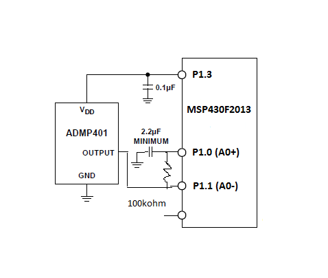
I use SD16 with ADMP401 MEMS microphone. The ADMP401 MEMS microphone' s Output DC Offset is 0.8 V. But SD16 max input voltage is 0.6 V. Are they compatible with each other ?

I want to use SD16 pre-amp required to boost the audio signal to a usable level.

How can i use MEMS microphone with MSP430F2013 ? 

  • selami tastan said:
    But SD16 max input voltage is 0.6 V

    No.maximum differential input voltage is +-0.6V. The absolute input voltage is limited by AVCC.

    So if you set the negative input to 0.8V, you can measure an analog signal of 0.2V to 1.4V.

    selami tastan said:
    I want to use SD16 pre-amp required to boost the audio signal to a usable level.

    Why not? Just use it. It amplifies the difference between negative and positive input, before conversion.
    The gain is in the backcoupling of the input differential amplifier, so it applies to the difference, not to the absolute input signal.

  • Hi Jens-Michael,

    I used ADMP401 Mems microphone with MSP430F2013 as in the picture below. 

    I did get the audio signal, but not very clean. 

    Can you suggest a solution ?

    The output of the audio signal as follows.

  • Here is the SD16 configuration code :

    BCSCTL1 = CALBC1_8MHZ; // Set range
    DCOCTL  = CALDCO_8MHZ; // Set DCO to 8 MHz (MCLK = SMCLK = 8 MHz)

    P1DIR   |= BIT3; // P1.3 output
    P1OUT |= BIT3;

    SD16CTL = SD16REFON + SD16SSEL_1 ; // 1.2V ref, SMCLK

    SD16INCTL0 = SD16GAIN_32 + SD16INCH_0;

    SD16AE = SD16AE0 + SD16AE1;  // A0+/-
    //Set ADC sample rate = 8ksps
    //SD16OSR1 SD16OSR0 ==> 1024 OSR    Fs = Fm/OSR ==> Fm (=f(SD16)) is typically around 8Mhz
    SD16CCTL0 = SD16DF + SD16IE + SD16OSR_1024; // Conts. conv, interrupt

    SD16CCTL0 |= SD16SC; // Start SD16 conversion

  • selami tastan said:
    I used ADMP401 Mems microphone with MSP430F2013 as in the picture below. 


    The circuit, as you have drawn it, won't work.
    You'll need a resistor between the positive signal input and GND. 1MOhm or so will be enough. This is to allow the internal OpAmps input BIAS current to flow. If you decouple an OpAmp input by an ideal capacitor, the bias current cannot flow and the input will get a raising offset voltage. With a non-ideal capacitor, the signal will at least be distorted.

    More about this here.

  • Jens-Michael Gross said:
    You'll need a resistor between the positive signal input and GND. 1MOhm or so will be enough.

    Ok. I put 1M ohm between the positive signal input and GND. It reduced the noise a little bit , but unexpectedly increased the amplitude of the sinus signal that as illustrated below.

  • selami tastan said:
     It reduced the noise a little bit , but unexpectedly increased the amplitude of the sinus signal that as illustrated below.

    My Guess (and it's only a guess without more measurement) is that teh previous noise was distortion of the sinus signals because of the offset voltage caused by the biasing.
    Now this distortion noise has been joined back into the original sinus signal.

    If you look closer at your screenshot, you'll see that the remaining noise mostly consolidates in visible small frequency ranges too, which are apparently harmonic overtones of the base sinus signals.

    After all, this looks quite good for a low-cost hardware :)

  • Jens-Michael Gross said:
    which are apparently harmonic overtones of the base sinus signals.

    Yes, you are right. Like you, I thought so.

    But I can not figure out how can i clear this distortion noise has been joined back into the original voice signal.


  • selami tastan said:
    But I can not figure out how can i clear this distortion noise has been joined back into the original voice signal.

    When you have a distorted sine signal of, say 1W, then you have 0.9W power on the sine frequency and 0.1W more or less evenly distributed to other frequencies (pink noise). (if it is harmonic distortion due to frequency-dependent feedbacks or resonances, the distribution if of course not evenly and therefore it isn't noise but rather 'ringing' overtones). When you remove the cause of the distortion, the power on the base sine frequency increases the same amount the distortion noise decreases. That's what I meant with 'joined back'.

    On a voice signal, of course distortion causes a power loss too on the plain voice signal. However, since  voice signal is mixed frequency anyway, it isn't clear to see, and the energy resolution of your diagram isn't high enough to see the difference.

    I have used this view often and the diagram window looks 1:1 like the one I had on Cool Edit about 10 years ago. Looks like Adobe has (once again) copied shamelessly (or maybe even bought a competitor). Not much difference between Adobe and Microsoft in this field ofoperation :)
    It's great for qualitative analysis (I used it to locate and - with a filter - remove a crying baby or other distortions from a concert record where I was one of the artists) but for quantitative analysis, it hasn't enough colors (and the human eye doesn't differentiate enough)

  • selami tastan said:

    I did get the audio signal, but not very clean. 

    Can you suggest a solution ?

    Try this 

    Peter

  • I thank you for your very valuable information.

**Attention** This is a public forum