This thread has been locked.

If you have a related question, please click the "Ask a related question" button in the top right corner. The newly created question will be automatically linked to this question.

creating an SPI clock output?

Other Parts Discussed in Thread: TRF7970A, MSP430FG4618

Hi all.

I'm using the MSP430FG4618 to control the TRF7970a NFC chip (by TI), hopefully making the two interact via SPI communication.

I'm quite new to MSP430, and I need to make a data_clk (aka SPI_CLK) triggering the SPI from the MCU to the NFC chip.

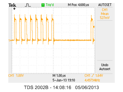
I have some sample code d/l from TI, showing how to create this clock, but it's not totally understandable to me, plus the clock signal is a bit jerky and has weird 'duty cycle' (see figure).

According to the NFC chip's manual, I need this duty cycle behavior for some reason, but I don't understand how is it controlled by the code.

SO - can anyone give me a code for a function that generates an SPI clock at about 2MHZ, and explain to me how to obtain this 'pull-down' behavior, like in this figure?

btw - output signal should be on P3.3

Thanks

  • Aviv Eben said:
    clock signal is a bit jerky and has weird 'duty cycle' (see figure).

    Clock seems to be more or less fine, especially if we take in account very low res JPG picture aliasing effects. I do not see any duty cycle problems either.

    Aviv Eben said:
    SO - can anyone give me a code

    You shall check webpage below for sites where "give me a code" question is appropriate:

    http://www.hongkiat.com/blog/50-freelance-job-sites-for-designers-programmers-best-of/

    Aviv Eben said:
    SPI clock at about 2MHZ

    This falls into "high speed clock" category, especially if you are doing breadbording and use logic analyser with pathetic 24MHz sampling freq. If you are beginner then I suggest you to start with something like 100KHz, then move to higher speeds when you get familiar with hardware (SPI peripheral, it's registers and usage for instance).

    Aviv Eben said:
    btw - output signal should be on P3.3

    You can't request SPI peripheral clock to appear on any arbitrary pin. Please refer to chip datasheet.

  • Ilmars said:

    Clock seems to be more or less fine, especially if we take in account very low res JPG picture aliasing effects. I do not see any duty cycle problems either.

    That was just a figure from TI's user guide. My clock looks like this:

    By 'duty cycle problem' I actually meant that the clock is not periodic like a clock should be, but is shifting to '0' after 8 pulses, which is what apparently should be according to the TI figure, but I don't understand what section in the code tells it to behave like this. 

    Ilmars said:

    You shall check webpage below for sites where "give me a code" question is appropriate:

    http://www.hongkiat.com/blog/50-freelance-job-sites-for-designers-programmers-best-of/

    I don't understand why requesting for a sample code is inappropriate.

    Ilmars said:

    This falls into "high speed clock" category, especially if you are doing breadbording and use logic analyser with pathetic 24MHz sampling freq. If you are beginner then I suggest you to start with something like 100KHz, then move to higher speeds when you get familiar with hardware (SPI peripheral, it's registers and usage for instance).

    I need exactly a 2MHZ frequency without getting too deep into understanding the hardware , that's why I'm looking a 'black box' function.

  • Aviv Eben said:
    I need exactly a 2MHZ frequency without getting too deep into understanding the hardware

    2MHz is freq when PCB layout, i/o impedance starts to impact signal quality, it's already visible on your scope as overshoot spikes and slight ringing - not critical, but it's there. I would add impedance-match series resistors for 2MHz lines.

    Aviv Eben said:
    but is shifting to '0' after 8 pulses

    This is how SPI works - one clock pulse for one data bit sent. When SPI transmit shift register is empty, clock is stopped. The faster you run SPI, the bigger pauses will be - because CPU becomes bottleneck here. If you need steady SPI transmission - use DMA controller.

  • Aviv Eben said:
    I don't understand why requesting for a sample code is inappropriate.

    Because you shall do your job yourself.

    When someone else do job for you, you shall pay for it.

    Commerce is not allowed here.

  • Yeah, but there is a reason why it is called a "sample code"...Or maybe it's just crazy me?

  • Aviv Eben said:

    Yeah, but there is a reason why it is called a "sample code"...Or maybe it's just crazy me?

    Honestly I can't find wording "sample code" in sentence: "SO - can anyone give me a code for a function that generates an SPI clock at about 2MHZ". If this is just typing error - then let's concentrate on your SPI questions. Honestly I think TI have quite good SPI samples and there's nothing more needed to get used to SPI usage :)
    To answer your 2MHz SPI clock: you shall read SPI peripheral user manual for your msp430 series, read about SPI clock options and clock divider. Everything is there.
  • Aviv Eben said:
    I actually meant that the clock is not periodic like a clock should be, but is shifting to '0' after 8 pulses, which is what apparently should be according to the TI figure, but I don't understand what section in the code tells it to behave like this. 

    Nothing in the code does. The SPI hardware is designed this way and it is designed this way because this is how SPi works:

    SPI is synchronous. One clock pulse, one bit. No bits to send, no clock pulses.

    When you write a byte to TXBUF, the USCI module shifts out 8 bits with 8 clock pulses at the frequency you defined by the module clock and the clock divider.

    If you don't put the next byte into TXBUF in time, there is nothing more to send and therefore no more clock pulse to be generated.

    In other words: your software is simply too slow to feed the SPI for a continuous transmission. This happens easily if the SPI clock speed is in the same magnitude as MCLK: If SPICLK == MCLK, then you have exactly 8 MCLK cycles to read the next byte from memory and stuff it to TXBUF if wou want a continuous data streem. 8 cycles exactly, not slower, but also not faster (and you don't have enough clock cycles to check for TXIFG or use interrupts for synchronization.)

    For bulk transfers, you shoudl consider setting up a DMA channel, which only takes 4 clock cycles per byte (includign synchronization) and leaves 50% of the MCLK cycles to the CPU for other jobs. I did so for the 512 byte transfers from and to SD cards.

**Attention** This is a public forum