This thread has been locked.

If you have a related question, please click the "Ask a related question" button in the top right corner. The newly created question will be automatically linked to this question.

MSP430F2012

Other Parts Discussed in Thread: MSP430F2012

Hello All,

I have been working on the following code, and am asking for help with ways to improve and debug it.

1.The switch determines which code will be ran.

2. Program 1 outputs a 5ms x 10ms on P1.2

3. Program 2 outputs P1.1 high for the duration P1.2 is on. P1.1 then goes low for a 500 microseconds and high for 500 micro seconds. P1.2 is high for 2.5 milliseconds, and then runs at 15kHz for 1.5 milliseconds

Any feedback on improvements and getting the following code to work would be greatly appreciated.


//SCR High Side-Low Side driver software for the MSP430F2012. The software is capable of two programs selected by a switch.
//Program 1 outputs a PWM [10ms period,50% duty cycle]on the low side.
//Program 2 outputs a Peak and Hold signal [5ms x 10ms] with high side clamping.
//P1.1 = High Side P1.2 = Low Side

#include <msp430f2012.h>
#include <msp430.h>

void main(void)                   
{
 
  WDTCTL = WDTPW + WDTHOLD;      //Stop Watch Dog Timer
 
 
 //Configure Switch (Choose Program A or B)
 
                    //Declares P1.0 input for reading the switch
    
  if(analogRead(P1IN)<0.5)           //Program A (Continous 5ms x 10ms on Low Side)
  {
 
  BCSCTL1 = CALBC1_1MHZ;         //Set range
  DCOCTL = CALDCO_1MHZ;          //SMCLK = DCO = 1MHz
  P1DIR |= (BIT2);               //Set P1.2 [Low Side] to output direction
  P1SEL |= (BIT2);               //Declares  TA1 & Turns on High Side
  TACTL= MC_1 + TASSEL_2;        //Tells CCR0 to count up with SMCLK
  TACCTL1=OUTMOD_7;              //Sets Set/Reset Mode with TACCR1
  TACCR0=10000-1;                //Set CCR0 to 100 Hz (10ms Period)
  TACCR1=5000;                   //Sets 50% duty cycle
 
  while(1){}                     //Runs Continously
  }
 
  else                        // Program B (Peak and Hold)
  { 

 //Step 1 (High Side & Low Side Static for 2.5 ms or by I=1A)
   
  P1OUT = 0;                     //Initializes P1.0 to off state 
  P1DIR = BIT1;                  //Sets P1.1 to output direction
  P1DIR = BIT2;                  //Sets P1.2 to ouput direction
  P1OUT |= BIT1;                 //Turns P1.1 on statically
  P1OUT |= BIT2;                 //Turns P1.2 on statically
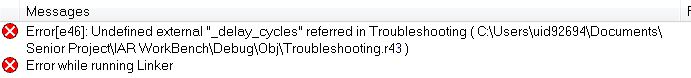
  _delay_cycles(39745);          //2.5 ms hold time
 
 //Step 2 (High Side=Static Low Side=15 kHz)
  
  BCSCTL1 = CALBC1_1MHZ;         //Set range
  DCOCTL = CALDCO_1MHZ;          //SMCLK = DCO = 1MHz
  P1DIR |= (BIT2);               //Set P1.2 to output direction
  P1SEL |= (BIT2);               //Declares  TA1 & Turns on High Side
  TACTL= MC_1 + TASSEL_2;        //Tells CCR0 to count up with SMCLK
  TACCTL1=OUTMOD_7;              //Sets Set/Reset Mode with TACCR1
  TACCR0=66-1;                   //Set CCR0 to 15 kHz (Hold Frequency)
  TACCR1=33;                     //Sets 50% duty cycle
  _delay_cycles(23848);          //1.5ms hold time
               
 //Step 3 (High side clamp on P1.1)
  
  P1OUT &= ~BIT1;                //Turns P1.1 off
  P1OUT &= ~BIT2;                //Turns P1.2 off
  _delay_cycles(8000);           //500 microsecond clamp
  P1OUT |= BIT1;                 //Turns P1.1 on
  _delay_cycles(8000);           //500 microsecond on time
  P1OUT &= ~BIT1;                //Turns P1.1 off
 
  while(1){}
  }
}


  • Split your project into parts, debug each part individually to find where exactly you fail in your code.

    Approach "here's my code, it does not work. please fix it" usually is not welcome. You shall show that you care and tried hard. So show us what exactly you tried and what was results.

  • Sorry if it came off that way, but I will try splitting it into parts and reply back after.

  • Sorry for the long delay inbetween post, as I got caught up in other projects at work. I have split the code into sections and verified what is working. The main issue I am having right now is the _delay_cycles function, as it is not recognized in IAR workbench. I simply need to delay inbetween commands, allowing time for the desired voltage signal to be achieved. I have tried a couple other methods of delay, but can not seem to get any to work properly. Is there a specific library I am missing to be able to use  _delay_cycles?

  • In IAR you have to use __delay_cycles rather than _delay_cycles

    i.e. use a prefix of two underscores rather than one.

  • Thank you,

     That solved many errors I was recieving. Everything is running properly except one minor issue now.  I am trying to create a peak and hold based signal, and PWM through delays. When ran individually, each part does a expected. The one issue I am having is in step 4, which is not stopping  the PWM from Step 2 when ran together. Is there specific logic from stopping PWM? As I have tried various Off commands and they are not working.

     //Step 2 (High Side=Static Low Side=15 kHz)

      P1SEL |= (BIT2);               //Declares  TA1 & Turns on High Side
      TACTL= MC_1 + TASSEL_2;        //Tells CCR0 to count up with SMCLK
      TACCTL1=OUTMOD_7;              //Sets Set/Reset Mode with TACCR1
      TACCR0=66-1;                   //Set CCR0 to 15 kHz (Hold Frequency)
      TACCR1=33;                     //Sets 50% duty cycle
      __delay_cycles(1500);          //1.5ms hold time
     
     //Step 3 (High side clamp on P1.1)
      
      P1OUT &= BIT1;                //Turns P1.1 off
      P1OUT &= BIT2;                //Turns P1.2 off
      __delay_cycles(500);             //500 microsecond clamp
      P1OUT |= BIT1;                 //Turns P1.1 on
      __delay_cycles(500);             //550 microsecond on time
     
      //Step 4 (5ms off time)
      P1OUT &= BIT1;                //Turns P1.1 off
      P1OUT &= BIT2;                //Turns P1.2 off
      __delay_cycles(5000);          //5ms delay
      
      }}

  • Joshua Hatfield said:
    Is there specific logic from stopping PWM

    You can switch the OUTMOD of the CCR unit to 0, which will set the poutput to the value of teh OUT bit rather than toggling/settign/resetting it with the compare event. It can be used for stopping the PWM as well as for forcing 0% or 100% dut cycle.
    Clearing ht ePxOUT bit will turn th eport pin into input mode, leaving it viulnerable to crosstalk from other channels.

  • Thanks for the advice. The code is semi working now with the advice given from everyone. The desired pulse is produced, and then two incorrect pulses are outputted. This is repetitive, and is shown below in the image of P1.1 voltage (blue), and the current (yellow) . The first and last pulse are correct, with two incorrect pulses inbetween. What is the root cause of the MCU not repeating the pulse consistently? I am running an infinite while loop, which i assume to be fine. Please let me know any pointers on getting this issue resolved. The code used is shown below.

    #include <msp430f2012.h>
    #include <msp430.h>

    void main(void)                   
    {
     
      BCSCTL1 = CALBC1_1MHZ;         //Set range
      DCOCTL = CALDCO_1MHZ;          //SMCLK = DCO = 1MHz
      P1OUT = 0;                     //Initializes P1.0 to off state
      P1DIR = BIT1 + BIT2;           //Sets P1.1 + P1.2 to output direction
     
      while (1)
      {
       
     //Step 1 (High Side & Low Side Static for 2.5 ms or by I=1A)
       
      P1OUT |= BIT1;                 //Turns P1.1 on statically
      P1OUT |= BIT2;                 //Turns P1.2 on statically
      __delay_cycles(2000);          //2 ms hold time
     
     //Step 2 (High Side=Static Low Side=15 kHz)

      P1SEL |= (BIT2);               //Declares  TA1
      P1OUT |= BIT1;                 //Turns P1.1 on statically
      TACTL= MC_1 + TASSEL_2;        //Tells CCR0 to count up with SMCLK
      TACCTL1=OUTMOD_7;              //Sets Set/Reset Mode with TACCR1
      TACCR0=66-1;                   //Set CCR0 to 15 kHz (Hold Frequency)
      TACCR1=33;                     //Sets 50% duty cycle
      __delay_cycles(2000);          //2ms hold time
     
     //Step 3 (High side clamp on P1.1)
     
      TACCR1=0;                      // 0% duty cycle
      P1OUT &= BIT1;                 //Turns P1.1 off
      P1OUT &= BIT2;                 //Turns P1.2 off
      __delay_cycles(500);           //500 microsecond clamp
      P1OUT |= BIT1;                 //Turns P1.1 on
      __delay_cycles(500);           //500 microsecond on time
     
      //Step 4 (5ms off time)

      P1OUT &= BIT1;                 //Turns P1.1 off
      P1OUT &= BIT2;                 //Turns P1.2 off
      __delay_cycles(5000);          //5ms delay
     
      }}

**Attention** This is a public forum