Other Parts Discussed in Thread: MSP430G2553, TLC59116
Hello, I'm having a similar problem here. But the solution does not reside on the address (unfortunately).
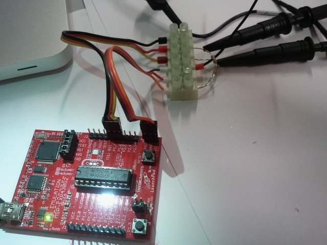
I'm trying to interface a TLC59116 with a MSP430G2553.
Here's my code:
//******************************************************************************
// Program Name - Short Description
//
// Description:
//
// /|\ /|\
// TLC59116 10k 10k MSP430G2xx3
// slave | | master
// ----------------- | | -----------------
// | P27/SDA|<-|----+->|P1.7/UCB0SDA XIN|-
// | | | | |
// | | | | XOUT|-
// | P26/SCL|<-+------>|P1.6/UCB0SCL |
// | | | |
//
// xxxx
// xxxx
// June 2013
// Built with CCS Version 5.3.0
//******************************************************************************
#include <msp430.h>
#include <stdint.h>
#define TLC59116_ADR 0xD0 // this is the allcall address
#define MODE1 0x00
#define MODE2 0x01
#define PWM0 0x02
#define PWM1 0x03
#define PWM2 0x04
#define PWM3 0x05
#define PWM4 0x06
#define PWM5 0x07
#define PWM6 0x08
#define PWM7 0x09
#define PWM8 0x0A
#define PWM9 0x0B
#define PWM10 0x0C
#define PWM11 0x0D
#define PWM12 0x0E
#define PWM13 0x0F
#define PWM14 0x10
#define PWM15 0x11
#define GRPPWM 0x12
#define GRPFREQ 0x13
#define LEDOUT0 0x14
#define LEDOUT1 0x15
#define LEDOUT2 0x16
#define LEDOUT3 0x17
#define SUBADR1 0x18
#define SUBADR2 0x19
#define SUBADR3 0x1A
#define ALLCALLADR 0x1B
#define IREF 0x1C
#define EFLAG1 0x1D
#define EFLAG2 0x1E
unsigned char *PTxData; // Pointer to TX data
unsigned char TXByteCtr;
unsigned char TxDataBuff[] = {0x00, 0x00, 0x00, 0x00};
void init_I2C(void);
void init_TCL59116(void);
void i2c_write(unsigned char reg, unsigned char val);
int main(void)
{
WDTCTL = WDTPW + WDTHOLD; // Stop WDT
P1SEL |= BIT6 + BIT7; // Assign I2C pins to USCI_B0
P1SEL2|= BIT6 + BIT7; // Assign I2C pins to USCI_B0
init_I2C();
init_TCL59116();
i2c_write(LEDOUT0,0x02);
__bis_SR_register(LPM0 + GIE); // LPM0 with interrupts enabled
}
void i2c_stop(void)
{
while (UCB0CTL1 & UCTXSTP);
}
void i2c_start(void)
{
UCB0CTL1 |= UCTR + UCTXSTT;
}
void i2c_write(unsigned char reg, unsigned char val)
{
i2c_stop();
TxDataBuff[0] = reg;
TxDataBuff[1] = val;
PTxData = TxDataBuff;
TXByteCtr = 2;
i2c_start();
__bis_SR_register(CPUOFF + GIE); // Enter LPM0 w/ interrupts
}
void init_TCL59116(void)
{
i2c_write(MODE1,0x01);
i2c_write(MODE2,0x01);
i2c_write(PWM0,0xFF);
i2c_write(IREF,0x00);
i2c_write(MODE1,0x01);
i2c_write(MODE1,0x01);
i2c_write(MODE1,0x01);
}
void init_I2C(void)
{
UCB0CTL1 |= UCSWRST; // Enable SW reset
UCB0CTL0 = UCMST + UCMODE_3 + UCSYNC; // I2C Master, synchronous mode
UCB0CTL1 = UCSSEL_2 + UCSWRST; // Use SMCLK, keep SW reset
UCB0BR0 = 120; // fSCL = SMCLK/120 = ~ very slow :)
UCB0BR1 = 0;
UCB0I2CSA = TLC59116_ADR; // Slave Address
UCB0CTL1 &= ~UCSWRST; // Clear SW reset, resume operation
IE2 |= UCB0TXIE; // Enable TX interrupt
}
#pragma vector = USCIAB0TX_VECTOR
__interrupt void USCIAB0TX_ISR(void)
{
if (TXByteCtr) // Check TX byte counter
{
UCB0TXBUF = *PTxData++; // Load TX buffer
TXByteCtr--; // Decrement TX byte counter
}
else
{
UCB0CTL1 |= UCTXSTP; // I2C stop condition
IFG2 &= ~UCB0TXIFG; // Clear USCI_B0 TX int flag
__bic_SR_register_on_exit(CPUOFF); // Exit LPM0
}
}
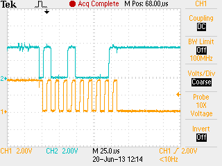
It gets stuck after the first i2c_start() call.
This is what I see when the I2C cable is connected to the TLC59116 board.
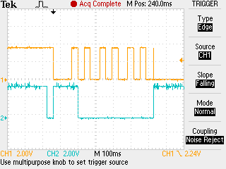
And this is what I see when the cable is UNPLUGGED (different address though)
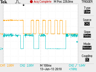
Why is SCL line forced low? Is this normal? It's not the slave that is forcing it Low because when the I2C wire is unplugged it is also being forced low. Oh, btw, I'm using two 10k pullup resistors.
Can you help me with this?
Thank you in advance