This thread has been locked.

If you have a related question, please click the "Ask a related question" button in the top right corner. The newly created question will be automatically linked to this question.

LM339N Comparator into MSP430G2231

Other Parts Discussed in Thread: TLV3202, TLV3404, LM339

Hello All,

I'm relatively new to microprocessors and electronics in general, but i understand the basic concepts.

So i'm having a bit of trouble interfacing an LM339N with an MSP430. I had a board designed that originally used AND gates off the comparitors to test if 8 inputs were above a reference voltage. I want to replace the AND gates with an MSP430 to put a 3 second time delay on the output instead of just turning it on as soon as an input is made. 

I used DIP switches to test the inputs to the MSP, so i know the code is working (i have an LED lit when all 8 inputs are on for 3 seconds) but i cannot get the LM339N to activate the MSP inputs.

I know that the LM339N needs a pull-up resistor on the output in order for the logic level to be high, but when the pull-up resistor is in there, there's current flow into the MSP430 inputs and the chip registers an input as high when it really isn't.

I've tried setting the internal pull-up and pull-down resisors on the MSP430 and i've also tried disabling them, and taking away the external pull-up all together. Nothing seems to work.

Is there another way i can get a LM339N output to interface with an MSP430 input?

Thanks

  • What voltage is the MSP430 running at? If you are running at 1.8V the MSP I/O negative going input threshold is 0.45V and an LM339N open collector output might struggle to get that low (full range guaranteed low is 0.7V). You might want to try a push-pull output comparator like the TLV3202 instead which has a lower VOL

  • If using the LM339N is important and VOL is the problem you could add a resistive divider (a pull-up to VDD on the LM339N output plus two resistors to VSS to divide down the VOL so that the MSP sees a lower voltage on the IO pin, at the mid point of the divider chain)

  • I'm using 3.3v supply for both the MSP and the LM339N.

    The actual chip itself isn't important, just the operation. I have quite a bit of circuitry tuned in for use with a comparator - i used a LM339N only because i've used them before. What are the advantages of a push-pull output? Can i drive the MSP input directly with a push-pull comparator?

    I'm really limited on board space so adding 2 more resistors per output (total of 16 more resistors) isn't too appealing. At this point however, i just want the thing to work so if i need 3 resistors per input for it to work i suppose that'll do. Any recommendations for that?

  • TLV3202 has a very low VOL push pull outputs  (unless you are wire or-ing the outputs (?)). A more equivalent part might be TLV3404 which is a quad open drain with 300mV max VOL

  • Well the Comparitor outputs are driving both LEDs and the input to the MSP - for visual indication of the input.

    Why are you so concerned about VOL? I"m confused. I'm trying to drive the output high.

  • Your original post says ' the chip registers an input as high when it really isn't.', which would happen if you were not driving the input low enough

  •   LM339N outputs are compatible with MSP430 inputs using internal pullups.

    You should post your code for review.

    ( One possible LM339 limitation you may be overlooking is the input common mode range. 

    The upper end of the common mode voltage range is VCC+ – 1.5 V = 3.3 -1.5 = 1.8V
     comparator will provide a proper output state as long as at least  one input remains in the common-mode range.)

    Peter


  • The code works but there's probably better ways to do what i want - like i said im new to the MCP and uP's in general.

    CODE:
    int main(void)
    {
    Grace_init(); // Activate Grace-generated configuration
    while(1){
    tcs = 0;
    // INPUT 1
    if ((P1IN & BIT0)) { // bit 0 high?
    tcs += 1;
    }
    // INPUT 2
    if ((P1IN & BIT1)) { // bit 1 high?
    tcs += 1;
    }
    // INPUT 3
    if ((P1IN & BIT2)) { // bit 2 high?
    tcs += 1;
    }
    // INPUT 4
    if ((P1IN & BIT3)) { // bit 3 high?
    tcs += 1;
    }
    // INPUT 5
    if ((P1IN & BIT4)) { // bit 4 high?
    tcs += 1;
    }
    // INPUT 6
    if ((P1IN & BIT5)) { // bit 5 high?
    tcs += 1;
    }
    // INPUT 7
    if ((P1IN & BIT6)) { // bit 6 high?
    tcs += 1;
    }
    // INPUT 8
    if ((P1IN & BIT7)) { // bit 7 high?
    tcs += 1;
    }
    // ENABLE OUT IF ALL INPUTS FOR ABOUT THREE SECONDS
    if (tcs == 8){
    count++;
    if (count >= 10700){
    secs++;
    count = 0;
    }
    if (secs >= 3){
    P2OUT = BIT6;
    }
    }
    else{// Drive P2.6 output low
    P2OUT = 0x00;
    secs = 0;
    }

    }
    }

    As far as the common mode range is concerned, if there's a 1.5v drop on the ouput, should i use a 5V supply for the comparator?

    I'm sorry i'm asking so many questions but i really don't fully understand all of this.

    I appreciate your patience and responses very much.

  • When you test with your DIP switches, are they in parallel with the open collectors of the LM339? Are your LEDs driven also by the LM339 open collectors (on when the output is low)?

  • The output saturation voltage of LM339 goes up considerably above 10mA, so if you are driving LEDs from the output the VOL will be relatively high (around 1V at 20mA for instance)

  • The initial test with the DIP switches were direct into the MSP. I replaced one of the DIP switch inputs with a LM339. I do not have the LEDs in the circuit yet as i hit this road block. 

    And i want the LEDs and MSP inputs to be on when the output is high.

    Would it be easier if i switched the logic to low = on?

  • I think it's worth taking a look at the actual voltage values when you have the DIP switch on (practically zero probably) and with the LM339 'low'. If you are sinking more than a few mA with the LM339 (if you have a small pull-up resistor in preparation for adding the LED across the open collector for instance) you might have an unexpectedly high voltage at the MSP input even when you expect the input to be 'low'

  • I just ran another test - I set all the DIP switches into the MSP as opposed to the LM339.

    My Voltage supply is 3.29V, and when the DIP switches are off, the Voltage at the MSP input pin is 0.0v (expected)

    When the DIP switch is on, the voltage at the MSP input is 3.29V. When all DIP switches are on, the output pin goes high and my LED turns on.

    I'm referencing all these voltages to ground.

    I'm using Grace to configure the inputs to use Pull-Down resistors.

  • OK maybe I misunderstood. So the problem is that when all of the LM339 outputs are (should be) high, you don't see them all as high (as opposed to low)? Have you verified that the LM339 outputs are indeed high? What voltage do you see on the MSP inputs when all of the LM339 outputs are high?

  • That's the nature of the problem.

    In order for the LM339 output to be high it needs a pullup resistor. However, when there's a pullup resistor on the output of the LM339, it's setting the MSP input high when the LM339 output is low.

    That's the main problem i'm running into - the LM339 NEEDS the pullup resistor in order to have a high output but that resistor puts a constant 'high' state into the MSP430 input.

  • On problem with the LM339 is that the inputs need to be 1.5V lower that the supply voltage in order for comparison to work properly. The inputs can be higher than that and not destroy the input pins, but the LM339 can't properly compare voltages higher than (supply voltage -1.5V). So if the supply voltage is 3.3V, then the Vref in your design cannot be higher than 1.8V.

  • my Vref right now is 1.65V. And the signal is coming straight from Vcc. So i'm comparing 1.65v reference with a 3.3v signal.

  • I suggest that you make the following test.

    (1) Do not change the software, use what you have shown us earlier.

    (2) Modify the hardware as shown in red here at one of the eight inputs:

    (3) Measure the voltage at x and also y when Sig < Vref

    (4) Measure the voltage at x and also y when Sig > Vref

    This is only a test, it will not solve you problem, but might tell use us (edit) what is wrong.

  • Brett Bernier said:
    my Vref right now is 1.65V. And the signal is coming straight from Vcc. So i'm comparing 1.65v reference with a 3.3v signal.

    Since your Signal ( Vcc  3.3 V ) is feeding the positive comparator input, the comparator output is being pulled high. 

    For the comparator to switch low (pull-down) the positive input (Vcc) must drop below 1.65V Vref. 

    Brett Bernier said:
    And the signal is coming straight from Vcc.

    This part doesn't make sense since neither the comparator or MSP430 will run at 1.65V Vcc

    Peter

  • Timothy Barr has found one problem with your design. “On problem with the LM339 is that the inputs need to be 1.5V lower that the supply voltage in order for comparison to work properly. The inputs can be higher than that and not destroy the input pins, but the LM339 can't properly compare voltages higher than (supply voltage -1.5V). So if the supply voltage is 3.3V, then the Vref in your design cannot be higher than 1.8V.”

    You say “my Vref right now is 1.65V. And the signal is coming straight from Vcc. So i'm comparing 1.65v reference with a 3.3v signal.”

    As you can see from the spec the LM339 is not guaranteed to work properly if either input level is within 1.5 volts of Vcc. So if you apply 3.3v you are violating the spec.

  • So this morning i had a fresh start on this issue and i have solved it - although its not the way i like.

    It seems i was trying to use the comparitor backwards instead of the way its intended. When the comparitor output is 'on' the current flows from Vss to GND through the collector. I didn't understand this concept before, but now that i do, i used the pullup resistor to send a constant high signal into the MSP and whenever the comparitor was 'on' that high level would be pulled to ground. I set the code for the MSP to look for low values, and everything is working fine now.

    My next step is getting actual OP-AMPS in place of comparitors because i want the HIGH value to be on, not the low value. 

    Thank you very much for all your help!

  • FYI comparitors are typically just specially tuned op-amp designs. If you want to switch the output state of the comparitor, then just switch the inputs. Just remember that because the LM339 is open collector it only draws current when the output is low. Any current when the output is off comes from the pull up resistor.

    http://en.wikipedia.org/wiki/Comparator

  • Brett Bernier said:
    Well the Comparitor outputs are driving both LEDs and the input to the MSP - for visual indication of the input.

    Oh, that's bad.
    I imagine you're connecting the LEDs to VCC (3.6V) and drive them low by the comparatior output?

    If so, it can't work. The comparator output has to drive the LED current. Which causes the oputput to go high. too high to be detected as low by teh MSP.

    Looking at the LM339N datasheet, the output saturation voltage is 0.2V for 6mA, 16mA; max. saturation voltage is 0.4V@16mA, but if you try to drive the LED with 20mA, saturation voltage will jump to the max, perhaps 2V (3.6V - LED voltage). Which is much too high to be ever deteced as low by the MSP.

    You may still use the LED, but you must limit the LED current to a few mA, so the comparator output can drive it low.

    On the other side, you don't need a pullup. When the output of the comparator is open, teh LED will connect the MSP pin to VCC. Since there is a very small input leakage current only (50nA), the LED forward voltage is small too. So the MSp pin will be on ~2.5V (guessed), which is high enough to be detected as high.

  • I suppose my wording there was incorrect.

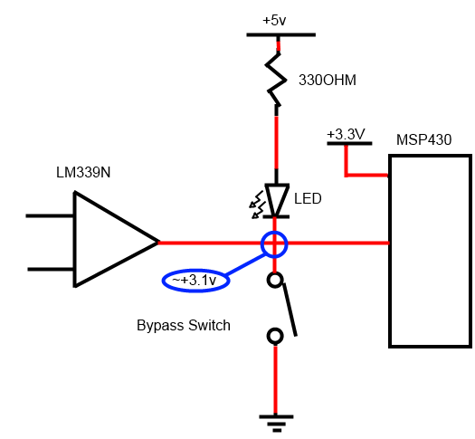
    This is how everything works:

    There's 5V sourcing the resistor and LED. Thanks to the voltage drop across the LED, the input of the MSP is held high at around 3.1 volts.

    When the comparator output is enabled, it completes the circuit to ground, allowing current flow through the led, lighting it, and dropping the MSP input pin to about zero volts. 

    I also put in a bypass switch that lets current flow directly through it to ground.

    So i set my MSP to look for a low signal. Everything works fine.

  • Brett Bernier said:
    There's 5V sourcing the resistor and LED. Thanks to the voltage drop across the LED, the input of the MSP is held high at around 3.1 volts.

    Assuming the comparator is off, ther eis a current path through resistor, diode and MSP pin clamp diode to VCC.

    The current will be as high as necessary, so that the voltage drop on the LED, resistor and clamp diode make up for 1.7V. It will likely be within the limits of 2mA for the clamp diode, but causes current consumption and makes the LED faintly glow.

    Now if the comparator is on, it tries to pull the MSP pin to GND. On 5V, asuming 1.7V LED forward voltage, there will be 10mA current. Fine for lighting the diode. But according to datasheet, 10mA result in a rather high voltage drop on the comparator output transistor. around or above 0.4V. That's okay to be accepted by the MSP as low.

    However, if you lower the diode resistor for higher current (most LEDs are specified for 20mA), the comparator output voltage drop will rise significantly. To a level where the MSP won't etect it as low-going anymore.
    If you decide to use 3V or less for the MSP, then the current into the clamp diode will rise and eventually destroy the MSP port pin.

    If it currently works, then fine. But keep in mind that changes on the design may break it. Or even parts from a different batch.

**Attention** This is a public forum