This thread has been locked.

If you have a related question, please click the "Ask a related question" button in the top right corner. The newly created question will be automatically linked to this question.

Spi slave reset problem

Other Parts Discussed in Thread: MSP430F5419A

Hi

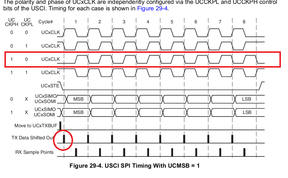
I'm using USCI_A on a  msp430f5419A set into slave mode:  3 pin , clock idle low,  sample on first edge ( ie rising edge ).

At startup everithing works fine. As it's a slave destinated to work in harsh environment I simulated some  spurious clock coming in.

The peripheral looses synchronization accounting for the number of spurious clock received as I expected so I thought to reset the spi at the end of a wrong received frame.

I simply toggled UCSWRST. Now the strange behaviour: the reset doesn't work completly; it always leads the peripheral to a state in which it is out of sync of one clock ie it seems that after the reset it has already a bit in the receive shift register. 

So if I inject five spurious clock then at first the peripheral is out of sync of 5 clocks, after reset it's out of sync of one clock.

If I inject three spurious clock then at first the peripheral is out of sync of 3 clocks, after reset it's out of sync of one clock.

Does anyone has any idea why this happens?

Any solution? 

  • It might be that you picked the wrong clock polarity/phase. So the 'idle' state of the bus might be identified as first half of the next clock.

    Generally, the chip select signal can be used for synchronization. Easiest is, if CS is de-asserted, reset the USCI. You may use 4-wire SPI mode to inhibit the clock input when CS de-asserts. This way, you can come out of reset immediately and prepare for the next transfer while being safe from spurious clock pulses until CS is asserted again. You should route the chip select to STE as well as to an interrupt.capable pin (P1/P2 or a timer capture pin), so you can detect the end of a transfer (and the beginning of the next too).

  • I have also tried by setting spi 4 wire and usign the CS. As I don't have the external CS I toggled the pullup - pulldown settings in order to assert - deassert it ( but I configured as STE through PxSEL ). I reset the spi while cs is de-asserted but the problem still remain. I toggle a pin on rx interrupt and I see that it is generated on the seventh clock rising edge instead of after the eigth -th. 

    As I mentioned the strange aspect is that I keep resetting the communication after each received frame ( 15 bytes ). Everithing is ok. Then I disturb the communication by sending external clock pulses. From this time the mulfunctionality appears ( but the reset is the same after each frame ).

    With the spi set such may, I noticed that if I want to transmit correctly I have to put the tx char on the tx buffer before the cs is asserted. As soon as the cs is asserted the first bit is sent out; the second bit is sent out on the first clock falling edge ... ie the transmission starts before clock pulses ( as reported on manual). Is it possible in some way that also the rx process sometimes starts on the cs assertion so that the byte reception completes on the seventh -th clock pulse?

    Anyway, for the moment the only workaround I found has been to implement the following sequence:

    UCA0CTL1 |= UCSWRST;
    UCA0CTL0 &= ~UCSYNC;
    UCA0CTL0 |= UCSYNC;
    UCA0CTL1 &= ~UCSWRST;

    Then everithing works. I can "disturb" the communication as I want but after the reset the rx interrupt is generated on the eigth clock pin correctly.

    But I don't understand why.

  • franco magrin said:
    As soon as the cs is asserted the first bit is sent out; the second bit is sent out on the first clock falling edge .

    Did you use the proper clock phase setting?

    franco magrin said:
    for the moment the only workaround I found has been to implement the following sequence:

    Indeed, apparently some things are not entirely reset when you set SWRST, unless you change something that directly influences the shift registers, like changing the SYNC mode. Note that this won't work on USCIB as the UCSYNC bit is R/O there.
    But a change between SPI and I2C and back might do the same.

  • My settings are :

    // Synronous mode, slave mode
    // External clock
    // Clock inactive is low
    // Data  captured on first UCLK edge and changed on the following edge.

    UCA0CTL0 = UCCKPH + UCSYNC + UCMSB + UCMODE_2 ;

    First bit sent out as soon as the cs is asserted ( as  per image ):

    But from the image first rx sample is on first UCLK rising edge. This doesn't work for me: that sample seems to be the second.

**Attention** This is a public forum