Other Parts Discussed in Thread: MSP430F2013
Hi all,
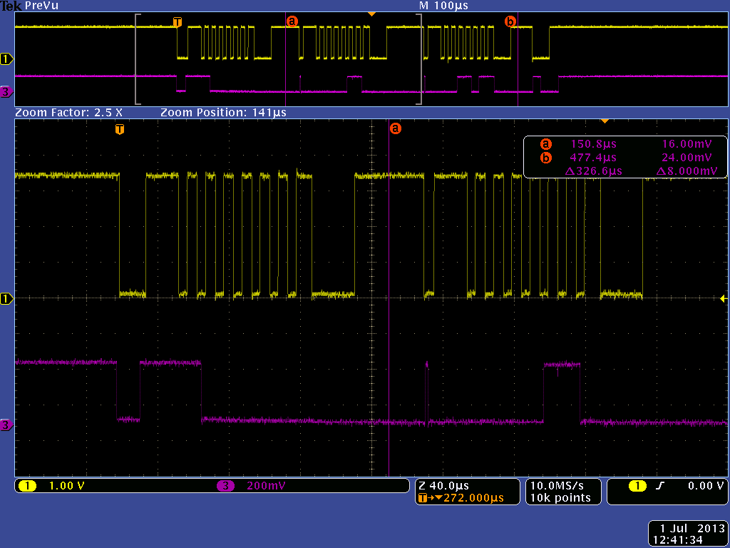
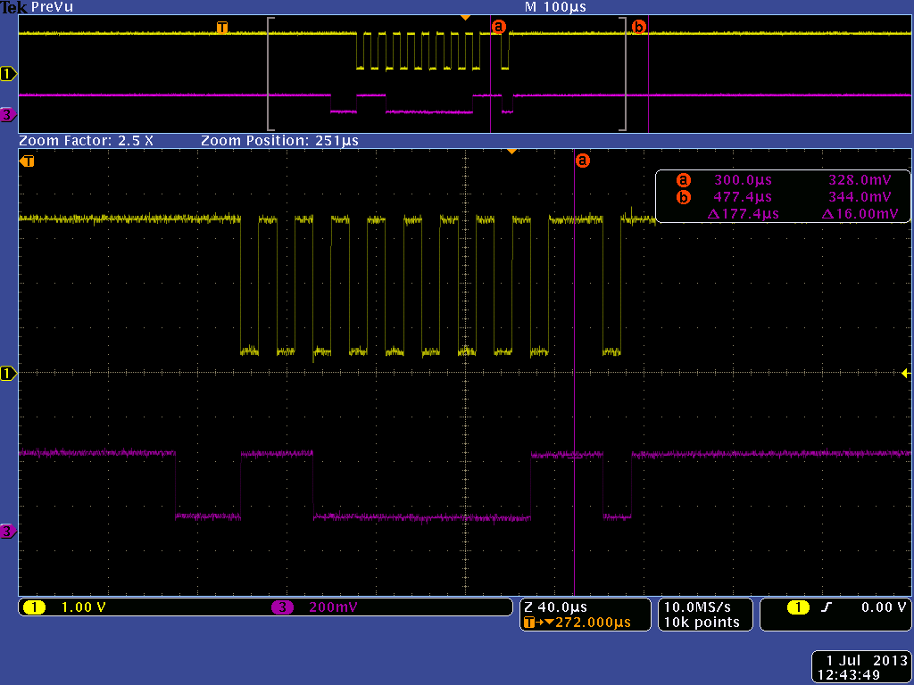
I have been trying to send commands to a slave device using the MSP430F2013 as a master. However, I keep running into the problem of not getting an ACK after sending the slave device address onto the bus, which means that a STOP condition occurs instead of the data actually getting sent across the bus. I tried using two devices already, and I am already sure that my addressing is correct (looked at the datasheets, and made sure to shift up have LSB 0 for write, etc). I have heard that there may be subtle timing issues, that if I change my C code with regards to the timing of all of the conditions (START condition, sending slave address, one cycle for ACK/NACK, etc), it may just start working. This seems to be the only thing I can think of, as it seems like my project does not acknowledge any slave device (There is only one master and one slave on the bus). My C code is below:
// MSP430F20xx Demo - I2C Master Transmitter / Receiver, multiple bytes
//
// Description: I2C Master communicates with I2C Slave using
// the USI. Master data should increment from 0x55 with each transmitted byte
// and Master determines the number of bytes received, set by
// the Number_of_Bytes value. LED off for address or data Ack;
// LED on for address or data NAck.
// ACLK = n/a, MCLK = SMCLK = Calibrated 1MHz
//
//
// ***THIS IS THE MASTER CODE***
//
// Slave Master
// (msp430x20x3_usi_15.c)
// MSP430F20x2/3 MSP430F20x2/3
// ----------------- -----------------
// /|\| XIN|- /|\| XIN|-
// | | | | | |
// --|RST XOUT|- --|RST XOUT|-
// | | | |
// LED <-|P1.0 | | |
// | | | P1.0|-> LED
// | SDA/P1.7|------->|P1.6/SDA |
// | SCL/P1.6|<-------|P1.7/SCL |
//
// Note: internal pull-ups are used in this example for SDA & SCL
//
// R. B. Elliott / H. Grewal
// Texas Instruments Inc.
// February 2008
// Built with IAR Embedded Workbench Version: 3.42A
//******************************************************************************
#include <msp430.h>
#define number_of_bytes 2 // (slave address), register, data <-- YES, THIS SHOULD BE TWO
//#define number_of_bytes 5 // How many bytes?
void Master_Transmit(void);
void Master_Receive(void);
void Setup_USI_Master_TX(void);
void Setup_USI_Master_RX(void);
void read(char reg, char data);
void write(char reg, char data);
char reg_var;
char data_var;
unsigned int test;
char MST_Data = 0x06;
//char MST_Data = 0x55; // Variable for transmitted data
char SLV_Addr = 0xC0;
//char SLV_Addr = 0x90;
// MST_Data starts as 0x06 (register) and then changes to 0x1B (data)
int I2C_State, Bytecount, Transmit = 0; // State variable
void Data_TX (void);
void Data_RX (void);
int main(void)
{
volatile unsigned int i; // Use volatile to prevent removal
WDTCTL = WDTPW + WDTHOLD; // Stop watchdog
if (CALBC1_1MHZ==0xFF) // If calibration constants erased
{
while(1); // do not load, trap CPU!!
}
DCOCTL = 0; // Select lowest DCOx and MODx settings
BCSCTL1 = CALBC1_1MHZ; // Set DCO
DCOCTL = CALDCO_1MHZ;
P1OUT = 0xC0; // P1.6 & P1.7 Pullups, others to 0
P1REN |= 0xC0; // P1.6 & P1.7 Pullups
P1DIR = 0xFF; // Unused pins as outputs
P2OUT = 0;
P2DIR = 0xFF;
while(1)
{
Master_Transmit();
//_NOP(); // Used for IAR
//while(1);
//Master_Receive();
//_NOP();
}
}
/******************************************************
// USI interrupt service routine
// Data Transmit : state 0 -> 2 -> 4 -> 10 -> 12 -> 14
// Data Receive : state 0 -> 2 -> 4 -> 6 -> 8 -> 14
******************************************************/
#pragma vector = USI_VECTOR
__interrupt void USI_TXRX (void)
{
switch(__even_in_range(I2C_State,14))
{
case 0: // Generate Start Condition & send address to slave
//P1OUT |= 0x01; // LED on: sequence start
Bytecount = 0;
USISRL = 0x00; // Generate Start Condition...
USICTL0 |= USIGE+USIOE;
USICTL0 &= ~USIGE;
if (Transmit == 1){ // WRITE
USISRL = 0x90; // Address is 0x48 << 1 bit + 0 (rw)
}
if (Transmit == 0){ // READ
USISRL = 0x91; // 0x91 Address is 0x48 << 1 bit
// + 1 for Read
}
USICNT = (USICNT & 0xE0) + 0x08; // Bit counter = 8, TX Address
I2C_State = 2; // next state: rcv address (N)Ack
__delay_cycles(10);
break;
case 2: // Receive Address Ack/Nack bit
USICTL0 &= ~USIOE; // SDA = input
USICNT |= 0x01; // Bit counter=1, receive (N)Ack bit
I2C_State = 4; // Go to next state: check (N)Ack
break;
case 4: // Process Address Ack/Nack & handle data TX
if(Transmit == 1){ // WRITE00000000000000000000000000
USICTL0 |= USIOE; // SDA = output
if ((USISRL & 0x01)) // If Nack received... /////////////////////////////////////////////////////////////////////////////////////////////////////////
{ // Send stop...
USISRL = 0x00;
USICNT |= 0x01; // Bit counter=1, SCL high, SDA low
I2C_State = 14; // Go to next state: generate Stop
P1OUT |= 0x01; // Turn on LED: error
}
else
{ // Ack received, TX data to slave...
USISRL = MST_Data; // <-- MY SPECIAL CASE, FIRST SEND TO DEVICE SHOULD BE REGISTER (0x06)
//USISRL = MST_Data++; // Load data byte
USICNT |= 0x08; // Bit counter = 8, start TX
I2C_State = 10; // next state: receive data (N)Ack
Bytecount++;
//P1OUT &= ~0x01; // Turn off LED
break;
}
}
if(Transmit == 0){ // READ
if (USISRL & 0x01) // If Nack received
{ // Prep Stop Condition
USICTL0 |= USIOE;
USISRL = 0x00;
USICNT |= 0x01; // Bit counter= 1, SCL high, SDA low
I2C_State = 8; // Go to next state: generate Stop
P1OUT |= 0x01; // Turn on LED: error
}
else
{
Data_RX();
} // Ack received
}
break;
case 6: // Send Data Ack/Nack bit
USICTL0 |= USIOE; // SDA = output
if (Bytecount <= number_of_bytes-2)
{ // If this is not the last byte
USISRL = 0x00; // Send Ack
P1OUT &= ~0x01; // LED off
I2C_State = 4; // Go to next state: data/rcv again
Bytecount++;
}
else //last byte: send NACK
{
USISRL = 0xFF; // Send NAck
P1OUT |= 0x01; // LED on: end of comm
I2C_State = 8; // stop condition
}
USICNT |= 0x01; // Bit counter = 1, send (N)Ack bit
break;
case 8: // Prep Stop Condition
USICTL0 |= USIOE; // SDA = output
USISRL = 0x00;
USICNT |= 0x01; // Bit counter= 1, SCL high, SDA low
I2C_State = 14; // Go to next state: generate Stop
break;
case 10: // Receive Data Ack/Nack bit
USICTL0 &= ~USIOE; // SDA = input
USICNT |= 0x01; // Bit counter = 1, receive (N)Ack bit
I2C_State = 12; // Go to next state: check (N)Ack
break;
case 12: // Process Data Ack/Nack & send Stop
USICTL0 |= USIOE;
if (Bytecount == number_of_bytes){// If last byte
USISRL = 0x00;
I2C_State = 14; // Go to next state: generate Stop
P1OUT |= 0x01;
USICNT |= 0x01; } // set count=1 to trigger next state
else{
P1OUT &= ~0x01; // Turn off LED
Data_TX(); // TX byte
}
break;
case 14:// Generate Stop Condition
USISRL = 0x0FF; // USISRL = 1 to release SDA
USICTL0 |= USIGE; // Transparent latch enabled
USICTL0 &= ~(USIGE+USIOE); // Latch/SDA output disabled
I2C_State = 0; // Reset state machine for next xmt
LPM0_EXIT; // Exit active for next transfer
break;
}
USICTL1 &= ~USIIFG; // Clear pending flag
}
void Data_TX (void){
USISRL = 0x1B; // <-- MY SPECIAL CASE, I'M ASSUMING THAT AFTER SENDING REGISTER BYTE (0x06), I NOW HAVE TO SEND DATA BYTE (0x1B)
//USISRL = MST_Data++; // Load data byte
USICNT |= 0x08; // Bit counter = 8, start TX
I2C_State = 10; // next state: receive data (N)Ack
Bytecount++;
}
void Data_RX (void){
USICTL0 &= ~USIOE; // SDA = input --> redundant
USICNT |= 0x08; // Bit counter = 8, RX data
I2C_State = 6; // Next state: Test data and (N)Ack
P1OUT &= ~0x01; // LED off
}
void Setup_USI_Master_TX (void)
{
_DINT();
Bytecount = 0;
Transmit = 1;
USICTL0 = USIPE6+USIPE7+USIMST+USISWRST; // Port & USI mode setup
USICTL1 = USII2C+USIIE; // Enable I2C mode & USI interrupt
USICKCTL = USIDIV_7+USISSEL_2+USICKPL;
//USICKCTL = USIDIV_0+USISSEL_2+USICKPL; // USI clk: SCL = SMCLK/128
USICNT |= USIIFGCC; // Disable automatic clear control
USICTL0 &= ~USISWRST; // Enable USI
USICTL1 &= ~USIIFG; // Clear pending flag
_EINT();
}
void Setup_USI_Master_RX (void)
{
_DINT();
Bytecount = 0;
Transmit = 0;
USICTL0 = USIPE6+USIPE7+USIMST+USISWRST; // Port & USI mode setup
USICTL1 = USII2C+USIIE; // Enable I2C mode & USI interrupt
USICKCTL = USIDIV_7+USISSEL_2+USICKPL; // USI clks: SCL = SMCLK/128
USICNT |= USIIFGCC; // Disable automatic clear control
USICTL0 &= ~USISWRST; // Enable USI
USICTL1 &= ~USIIFG; // Clear pending flag
_EINT();
}
void Master_Transmit(void){
volatile unsigned int i;
Setup_USI_Master_TX();
USICTL1 |= USIIFG; // Set flag and start communication
LPM0; // CPU off, await USI interrupt
for (i = 0; i < 5000; i++); // Delay between comm cycles
}
void Master_Receive(void){
volatile unsigned int i;
Setup_USI_Master_RX();
USICTL1 |= USIIFG; // Set flag and start communication
LPM0; // CPU off, await USI interrupt
for (i = 0; i < 5000; i++); // Delay between comm cycles
}
void read(char reg, char data)
{
reg_var = reg;
data_var = data;
Master_Transmit();
}
void write(char reg, char data)
{
reg_var = reg;
data_var = data;
Master_Receive();
}
Any help would be greatly appreciated.
Matt