Because of the holidays, TI E2E™ design support forum responses will be delayed from Dec. 25 through Jan. 2. Thank you for your patience.

This thread has been locked.

If you have a related question, please click the "Ask a related question" button in the top right corner. The newly created question will be automatically linked to this question.

Switch Bounce Questions

I understand my problem may be strictly hardware related, but the inconsistent behavior has me wondering if there is a software issue.  

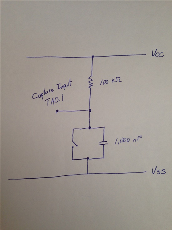
I am using a reed switch and a capture input.  The reed switch has been debounced to the best of my knowledge.  I have attached a picture of the circuit below.

The setting for the capture input are as follows.

void timer1AInit (void)
{
        // **** TIMERA1 CONTROL ****
        TA1CTL = TASSEL_1 + MC_1 + TACLR;

        // *** CHANNEL 0 ****
        TA1CCR0 = 30000;

        //**** CHANNEL 0 CONTROL ****
        TA1CCTL0 = CCIE;

        // **** CHANNEL 1 CONTROL ****
        TA1CCTL1 = CM_2 + CCIS_0 + SCS + CAP + CCIE;
}

I am having two issues.  

1.  I periodically have switch bounce at the end of the capture.  The input is held high and when the capture takes place it is grounded.  As the capture ends and the input goes back to high, I will get a number of captures but very rarely.

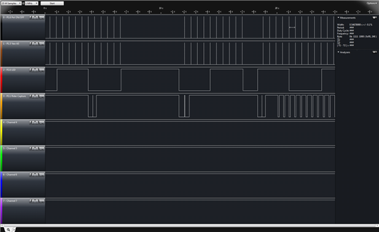
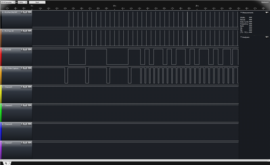
2.  If the capture takes a long period of time, there is a double capture in the middle of the capture.  I believe what is happening is that the ISR finishes before the capture ends, which clears the interrupt.  When this happens the capture records again.  I could be wrong and this may also be switch bounce related.  I have attached a screen shot from a logic analyzer.  The line of interest is line four. The first three captures show the double capture.  The last group of captures is when the speed of the captures increases.


As a final thought, if I toggle an LED each time a capture occurs the toggling gets out of sync.  It seems to work when the captures are slow but misses every fourth when the speed increases.  I am confused, because I can see the capture working but it seems the ISR is not getting called.  The LED is on line 3 and the captures are on line 4.

Any insight would be greatly appreciated.  

Take care,

Jon

  • Hi Jon,

    I don't quite follow what you are trying to do.  Are you using the capture as a software debounce?  Could you post the rest of your code? or at least the ISR's.

    Regards,

    Barry

  • Jonthornham said:
    ... The reed switch has been debounced to the best of my knowledge. ...

  • Did you check the hardware de-bounced signal with an oscilloscope? I think it is fine when you close the switch. But what does the waveform looks like when you open the switch?

    I think you will be much better off if you use software de-bounce.

  • Jonthornham said:

    1.  I periodically have switch bounce at the end of the capture. 

  • Thanks for the reply.  Let me explain what I am doing.

    I am using an MCU to measure and record wind angle on a bike.  When the rider is not moving, I have the MCU in LMP4.  When they start to ride a magnet attached to the spoke passes a reed switch and puts the MCU in LPM3, turns on the ADC10 and starts a timer.  If the timer times out before the next capture, the ADC is shut off, and it re-enters LMP4.  

    The switch bounce occurs as the magnet passes the reed switch.  I tried to debounce it with hardware but am not sure if I've done it correctly or if I cam having software issues.  

    The ISR for the capture simply resets a global variable that is checked in the timer's ISR.  If the global variable = 0 then it is set to 1.  If it's one (meaning the rider has stopped) it puts the MCU back in LPM4.  I have added the code for both ISR's below.  I used the LED for testing only so I could see what was going on.  Unfortunately, I do not have an oscilloscope.  If you need anything else please let me know.

    #pragma vector = TIMER1_A0_VECTOR
    __interrupt void RidingTimerISR(void)
    {
            /*------------- THIS WILL BE USED FOR THE SPEED TIMER. IF IT TRIPS WE REENTER LPM4 -----------------*/

            TA1CCTL0 &= ~CCIFG; // Clear the interrupt flag.


            if (timerCounter == 0)
            {
                    timerCounter = 1;

             }

            else if (timerCounter == 1)
            {

                    timerCounter = 0;

                    P2SEL &= ~BIT1; // Reset PinPin 9 to act as a Port Input pin for LPM4

                    _BIC_SR(LPM3_bits); // Exit LPM3

                   _BIS_SR(LPM4_bits + GIE); // Enter LPM4

            }

    }

    /*-------------------------------------------------------------------------------------------------------*/

    #pragma vector = TIMER1_A1_VECTOR
    __interrupt void RidingCaptureISR(void)
    {
    TA1CCTL1 &= ~CCIFG; // Clear the interrupt flag.

    // Reset the timerCount to zero so the ADC10 stays on and we stay in LPM3.
    timerCounter = 0;
    }

    /*-------------------------------------------------------------------------------------------------------*/

     Take care,

    Jon

  • Hi Jon,

    I agree with OCY that if you are unsure of you hardware debounce you should probably do a software debounce.

    I think you would have a more consistent timeout if you cleared and restarted the Timer in your TIMER_A1 ISR.  The way you have it setup, your timeout takes two roll-overs of the timer, but if TIMER A1 is entered and the flag cleared, and then the timer immediately rolls over and sets the flag you now in a sense only have one roll over causing a timeout.  If you set your CCR register to 60000 and then clear and restart your timer in the TIMER_A1 ISR then if your TIMER_A0 ISR is ever entered it is a timeout event.

    What frequency is you ACLK running?

    Regards,

    Barry

  • Barry,  

    Thanks for the response.  I am using the VLO.  Timing is not critical.  

    I've spent the last 3 hours looking at this trying to figure out what is happening. I think I've figured out some of it.

    The missing LED toggles in the last picture of my first post are due to the LCD.  In the Timer1_A0 ISR I was using delay cycles for the LCD and forcing myself to get stuck in the ISR.  Rookie mistake for a rookie I guess.

    Ultimately, the bounce I am experiencing is happening on the rising edge of the capture.  Since the timer is set up to capture on the falling edge it doesn't really matter.  

    I am however interested in the software debounce.  I spent some time looking through John Davies book and The Ganssle Groups site.  It seems challenging to set this up with limited timers.  The MSP430 I am using has two TimerA peripherals and I am using both.  Using TACCR2 would be challenging since I couldn't set and reset it as I pleased.  Am I missing something?

    Finally, your suggestion to clear the timer and reset it seems to be more resource intense then what I have running.  My understanding is that writing 1 to TACLR resets the entire timer.  That would mean that each capture ISR would need to reset the timer.  I could be wrong.  I am new to this.

    Take care,

    Jon

  • Jonthornham said:
    In the Timer1_A0 ISR I was using delay cycles for the LCD and forcing myself to get stuck in the ISR.  Rookie mistake for a rookie I guess.

    Many people do time-consuming things inside an ISR. THis is because in normal programming classes, you use threads (which are interrupted and scheduled by an OS). ISRs are no threads. They are exclusive, non-interruptable interruptions of the main thread. And should be fast-in, fast-out.

    If you need, you can setup a state machine. Do something, note what you have already done in a global variable and exit the ISR. On the next event, you knwo where you left and can continue. E.g. writing a command byte by byte to the LCD. Do one byte, exit the ISR, and on the next TX interrupt, writ eth next byte in the TX ISR.

    If you need to wait for a flag or for a certain time inside an ISR, there's something wrong in your concept.

    Jonthornham said:
    I am however interested in the software debounce.

    Search for 'debounce' in the forum. there have been many threads, including different concepts and even code or pseudo-code.

  • Jens-Michael,

    Thank you for your response.  I've been reading about state machine like you suggested.  I come from a software background so the concept of ISR's is a little foreign.  I have two questions if you have time.

    I am assuming calling a function inside an ISR is also a bad idea if the function were to take a long time to complete?  It seems like the lack of threads would hold the ISR until the function was complete.  

    I looked up state machines and found two sources of information.  The first was Tom Baugh's book "MSP430 State Machine Programming" and the second was a short document from TI.  Do you know of anything in between that explains the concept in detail with a few examples?  I searched the forum but did not find what I was looking for.  It seems like state machines are a major component I would be lost without.

    Take care,

    Jon

  • Jonthornham said:
    I am assuming calling a function inside an ISR is also a bad idea if the function were to take a long time to complete?  

    Right. But not only for the possibly long exdcution time. On a function call, some registers are clobbered, so the ISR needs to save them on stack. Also, the function itself will save some registers that it uses on stack. At the end you have a significant overhead in addition to the execution tiem of the funciton. And often, when you use ISRs, every clock cycle may count.

    Jonthornham said:
     I come from a software background so the concept of ISR's is a little foreign.

    You have to deal with it when writing device drivers on Linux or Windows. But for a normal application developer, it is rather uncommon.

    See it as the virtual and unforseen insertion of a function call to the ISR at the current point of execution. hile at the same tiem protecting the called function to be interrupted in the same way.
    ISRs are for reacting immediately on things that don't allow for a delay, outside of the normal chain of execution.

    BTW, threads on an MSP are not impossible. There are some 'operating systems' aailable for the MSP which provide multithreading.
    And I implemented a thread scheduler (with thread sleep and wakeup events and priorities) for the 5438. Took about 800 bytes of code plus some additional code for the event signaling in the low level module functions.

    Jonthornham said:
    Do you know of anything in between that explains the concept in detail with a few examples?

    A state machine quite simple. It is like a worker who writes down at the end of the day what to do next day. When he returns to work next day, he reads his own note and continues where he stopped. No matter what he did outside the office or how long it took to return to it. That's the concept. Do something and write down (in a global or a static local variable) what to do next.
    Teh state machine function can then be implemented as a huge switch statement. Each case is a state and before the break of each case, you set the switch argument (the state variable) to the state to execute next, and then you can exit the state machine function, not knowing where it was called from or caring for what happens next. Next time the function is called, the state variable tells where to continue.
    Just split the whole job into as many chunks as required to have each working step small enough to not take too much tiem to execute.
    In case you're waiting for something, you may even remain in the same state until the event you waited for has happened.

    Let's assume 'waiting' means '1':

    void statemachine(void){
    static usnigned char state = 0;
    switch (state){
      case 0:
        do what is to be done initially
        break;
      case 1:
        if (done waiting)
          state = 2;
      break;
      case 2:
        do what to be done after waiting
        state = 1; // wait again
      break;
    }
    }

    When you call this function the first time, it will do what to be done initially. On the second call it will do nothing, and so on the third and all future calls until the event it was waiting for has happened. Then it will do what has to be done and after that, ti will again wait.

  • Excellent info as usual.  Thanks for taking the time to write such a detailed response.  It' s a great help.

    Take care,

    Jon

**Attention** This is a public forum