This thread has been locked.

If you have a related question, please click the "Ask a related question" button in the top right corner. The newly created question will be automatically linked to this question.

MSP43F5510 SCL Held Low

Other Parts Discussed in Thread: MSP430F5510

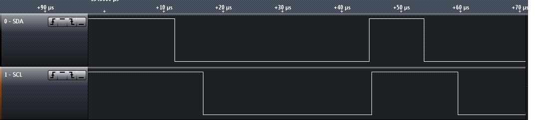
I am attempting to establish communication between a MSP430F5510 and a Newhaven LCD NHD‐0216K3Z‐FL‐GBW‐V3.  When I start the program the clock pin is high, then is pulled low by the MSP430 and stays low (same with SDA).  If I unplug the MSP430 from the bus it goes high again, so I know that it is the MSP430 pulling the bus low.  I am using a slightly modified version of the example I2C code, changing only the slave address and the data to be transmitted.

#include <msp430f5510.h>

unsigned char *PTxData; // Pointer to TX data
unsigned char TXByteCtr;

const unsigned char TxData[] = // Table of data to transmit
{
0xFE,
0x41,
0x72

};

void main(void)
{
unsigned int i;

WDTCTL = WDTPW + WDTHOLD; // Stop WDT
P3SEL |= 0x03; // Assign I2C pins to USCI_B0
UCB0CTL1 |= UCSWRST; // Enable SW reset
UCB0CTL0 = UCMST + UCMODE_3 + UCSYNC; // I2C Master, synchronous mode
UCB0CTL1 = UCSSEL_2 + UCSWRST; // Use SMCLK, keep SW reset
UCB0BR0 = 12; // fSCL = SMCLK/12 = ~100kHz
UCB0BR1 = 0;
UCB0I2CSA = 0x50; // Slave Address
UCB0CTL1 &= ~UCSWRST; // Clear SW reset, resume operation
UCB0IE |= UCTXIE; // Enable TX interrupt

while (1)
{
for(i=0;i<10;i++); // Delay required between transaction
PTxData = (unsigned char *)TxData; // TX array start address
// Place breakpoint here to see each
// transmit operation.
TXByteCtr = sizeof TxData; // Load TX byte counter

UCB0CTL1 |= UCTR + UCTXSTT; // I2C TX, start condition

__bis_SR_register(LPM0_bits + GIE); // Enter LPM0, enable interrupts
__no_operation(); // Remain in LPM0 until all data
// is TX'd
while (UCB0CTL1 & UCTXSTP); // Ensure stop condition got sent
}
}

//---------------- --------------------------------------------------------------
// The USCIAB0TX_ISR is structured such that it can be used to transmit any
// number of bytes by pre-loading TXByteCtr with the byte count. Also, TXData
// points to the next byte to transmit.
//------------------------------------------------------------------------------
#pragma vector = USCI_B0_VECTOR
__interrupt void USCI_B0_ISR(void)
{
switch(__even_in_range(UCB0IV,12))
{
case 0: break; // Vector 0: No interrupts
case 2: break; // Vector 2: ALIFG
case 4: break; // Vector 4: NACKIFG
case 6: break; // Vector 6: STTIFG
case 8: break; // Vector 8: STPIFG
case 10: break; // Vector 10: RXIFG
case 12: // Vector 12: TXIFG
if (TXByteCtr) // Check TX byte counter
{
UCB0TXBUF = *PTxData++; // Load TX buffer
TXByteCtr--; // Decrement TX byte counter
}
else
{
UCB0CTL1 |= UCTXSTP; // I2C stop condition
UCB0IFG &= ~UCTXIFG; // Clear USCI_B0 TX int flag
__bic_SR_register_on_exit(LPM0_bits); // Exit LPM0
}
default: break;
}
}

  • One problem I see in your code is that on the secodn loop, GIE is already set from previous loop when you set UCTXSTT. Sicne setting UCTXSTT causes an immediate TX interrupt, your ISR is executed before you enter LPM. In case of no byte to send, the ISR would exit LPM that is not entered yet, and then main will enter LPM that is never exited.

    Another problem is that you don't check for NACKIFG. If the slave doesn't respond, LPM will never exit. However, the MSP will try to end the transfer and waits for you to set UCTXSTP (or UCTXSTT for a repeated start). While waiting, it holds SCL low.

    Are you sure that 0x50 is the slave address? Often, what is presented as the slave address in teh datasheets is really a combined slave address with R/W bit. (especially if the datasheet gives two different 'slave addresses' for read and write. Try 0x28 as slave address. The R/W bit is automatically added bysed on the UCTR bit by the USCI.

  • Thanks for the reply.  I have implemented the NACKIFG case in the interrupt, but to no avail; the same issue still persists.  I am not quite clear on what you mean in your first paragraph, where you are talking about GIE being set when I set UCTXSTT.  If you could provide some more explanation I would appreciate it.  I have already tried 0x50 and 0x28 as the slave address, both to no avail.

    I borrowed a logic analyzer and got a picture of what the SCL and SDA lines are doing.  The both pulse once, then go low when I address 0x50.  When I address 0x28 they both go low and then stay there.

    This is a picture of what happens when I address 0x50.


    I modified two areas of the code, the interrupt enable at the beginning and case 4 of the interrupt.  I copied my changes below.

    UCB0IE |= UCTXIE + UCNACKIE;        // Enable TX, NACK interrupt

    case 4: // Vector 4: NACKIFG
    {
    UCB0CTL1 |= UCTXSTP; // I2C stop condition
    UCB0IFG &= ~UCNACKIFG; // Clear USCI_B0 NACK int flag
    __bic_SR_register_on_exit(LPM0_bits); // Exit LPM0
    break;
    }

    EDIT: fixed a typo

  • Andrew Haslem said:
     I am not quite clear on what you mean in your first paragraph, where you are talking about GIE being set when I set UCTXSTT.

    When entering LPM in the first loop (first execution of the while(1) loop), you set GIE. This allows for interrupts. (if you wouldn't, this would lead to an eternal sleep as no interrupt could happen that would wake the CPU from LPM).
    However, your ISR exits LPM but leaves GIE still set, so interrupts are still enabled after waking from LPM. When the while loop is executed the second time, interrupts are enabled from the beginning. Now setting UCTXSTT in transmitter mode causes an immediate TX interrupt request, which is handled before you go into LPM. The ISR will possibly wake the CPU from an LPM it wasn't in (which is no problem), but now it could happen that after you go into LPM there won't be any more TX interrupt, e.g. due to a communication error. So the MSP will remain in LPM forever.
    You need to clear GIE before you do anything that is synchronized with entering LPM. In the first loop execution, all is fine because GIE is cleared by default on CPU startup.

    You can handle this by adding GIE to the __bic_sr_register_on_exit intrinsic. Like you did when entering LPM.

    BTW: it isn't necessary to manually clear the UCNACKIFG bit. When reading UCB0IV for the switch, this bit is automatically cleared when the UCB0IV register returned 4 as highest pending interrupt.

    And don't use a for loop for delays. The outcome is uncertain. For a delay of a fixed numbe rof CPU cycles, use the __delay_cycles() intrinsic. Or use a timer. That's why timers were developed.

    Back to the original problem.

    The output looks weird. I don't see a proper clock signal and also the timing looks weird. Can you look at the lines iwht a scope? A logic analyzer, as useful as it might be, only tells its very own version of the real story. It interprets the line signals based on its own trigger levels etc. In reality, the signal might look completely different and give more information about what's happening.

    Some general questions (don't laugh, even experienced developers have fallen into these traps):
    Do you have proper pullup resistors on the lines (10k or less to VCC)?
    Do master and slave have a common GND connection?

    It almost looks like the MSP resets while it is sending the first bit of the address.

    You should declare your pointer and counter as volatile. If you don't, the compiler doesn't know that these variable smight be read outsiede the program flow (by an ISR) and it is possible that writing the new values to them is delayed and the ISR gets old values. in this case, the ISR could try to fetch the first byte from 0x0000 (uninitialized pointer). However, I don't see why this could cause a reset. YOu could try setting a breakpoint before the while loop and see whether it is triggered again after you passed it once. If it does, the MSP resets.
    Using the volatile keyword deactivates optimization for a variable and ensures that a read or write at the exact number of accesses and at the exact position where the instruciton is in the source code.
    (However, excessive use of volatile variables blocks optimization and leads to long and slow code).

  • I changed the loop to a __delay_cycles intrinsic.  I can change that over to a timer once I get the I2C working.  I also added GIE to the intrinsic on exit from the ISR.  I was also able to confirm that in order to write to what Newhaven says is 0x50 I need to write to 0x28, like you said.

    I have 10k pullup resistors on each line, but I did not have a common ground (oops...).  I fixed that and now I can get stuff to display on the LCD.  Kinda kicking myself that I did not think of the common ground line, but I can move forward now.

    For anybody else who may have this issue in the future, make sure that you have FETs between the LCD and the MSP430, as the LCD is 5v and the MSP430 is a 3.3v device.  The code that I just used to turn on the LCD and clear the screen is below.  A good app note on the 3.3v and 5v issue can be found here on pg 10:

    http://ics.nxp.com/support/documents/interface/pdf/an97055.pdf

    #include <msp430f5510.h>

    volatile unsigned char *PTxData; // Pointer to TX data
    volatile unsigned char TXByteCtr;
    unsigned char done = 0;

    const unsigned char TxData[] = // Table of data to transmit
    {
    0xFE,
    0x52,
    0x25,
    0xFE,
    0x53,
    0x07,
    0xFE,
    0x51,
    0xFE,
    0x46
    };

    void main(void)
    {
    WDTCTL = WDTPW + WDTHOLD; // Stop WDT
    P3SEL |= 0x03; // Assign I2C pins to USCI_B0
    UCB0CTL1 |= UCSWRST; // Enable SW reset
    UCB0CTL0 = UCMST + UCMODE_3 + UCSYNC; // I2C Master, synchronous mode
    UCB0CTL1 = UCSSEL_2 + UCSWRST; // Use SMCLK, keep SW reset
    UCB0BR0 = 12; // fSCL = SMCLK/12 = ~100kHz
    UCB0BR1 = 0;
    UCB0I2CSA = 0x28; // Slave Address
    UCB0CTL1 &= ~UCSWRST; // Clear SW reset, resume operation
    UCB0IE |= UCTXIE + UCNACKIE; // Enable TX, NACK interrupt

    while (!done)
    {
    __delay_cycles(100); // Delay required between transaction
    PTxData = (unsigned char *)TxData; // TX array start address
    // Place breakpoint here to see each
    // transmit operation.
    TXByteCtr = sizeof TxData; // Load TX byte counter

    UCB0CTL1 |= UCTR + UCTXSTT; // I2C TX, start condition

    __bis_SR_register(LPM0_bits + GIE); // Enter LPM0, enable interrupts
    __no_operation(); // Remain in LPM0 until all data
    // is TX'd
    while (UCB0CTL1 & UCTXSTP); // Ensure stop condition got sent
    }
    }

    //------------------------------------------------------------------------------
    // The USCIAB0TX_ISR is structured such that it can be used to transmit any
    // number of bytes by pre-loading TXByteCtr with the byte count. Also, TXData
    // points to the next byte to transmit.
    //------------------------------------------------------------------------------
    #pragma vector = USCI_B0_VECTOR
    __interrupt void USCI_B0_ISR(void)
    {
    switch(__even_in_range(UCB0IV,12))
    {
    case 0: break; // Vector 0: No interrupts
    case 2: break; // Vector 2: ALIFG
    case 4: // Vector 4: NACKIFG
    {
    UCB0CTL1 |= UCTXSTP; // I2C stop condition
    __bic_SR_register_on_exit(LPM0_bits + GIE); // Exit LPM0
    break;
    }
    case 6: break; // Vector 6: STTIFG
    case 8: break; // Vector 8: STPIFG
    case 10: break; // Vector 10: RXIFG
    case 12: // Vector 12: TXIFG
    if (TXByteCtr) // Check TX byte counter
    {
    UCB0TXBUF = *PTxData++; // Load TX buffer
    TXByteCtr--; // Decrement TX byte counter
    }
    else
    {
    UCB0CTL1 |= UCTXSTP; // I2C stop condition
    UCB0IFG &= ~UCTXIFG; // Clear USCI_B0 TX int flag
    done = 1;
    __bic_SR_register_on_exit(LPM0_bits + GIE); // Exit LPM0
    }
    default: break;
    }
    }

**Attention** This is a public forum