This thread has been locked.

If you have a related question, please click the "Ask a related question" button in the top right corner. The newly created question will be automatically linked to this question.

Unable to find the maximum amplitude in the analog ouput using DAC MSP430F6638

Other Parts Discussed in Thread: MSP430F6638

Hello Everyone,

I am a beginner to MSP430  and CCS v4 so please pardon my knowledge if i did not understand or ask basic concepts.

I am using the following code  for implementation of  DAC unit for MSP430F6638 using CCSv4.

#include <msp430f6638.h>

void main(void)

{

WDTCTL = WDTPW + WDTHOLD; // Stop watchdog timer

// AVcc is used as reference, calibration on, DAC on

DAC12_0CTL0 = DAC12IR + DAC12SREF_1 + DAC12AMP_5 + DAC12CALON;

DAC12_0CTL0 |= DAC12ENC; // Enable DAC12

DAC12_0DAT = 0x7FF; // ~1.5V

__bis_SR_register(LPM4_bits); // Enter LPM4

}

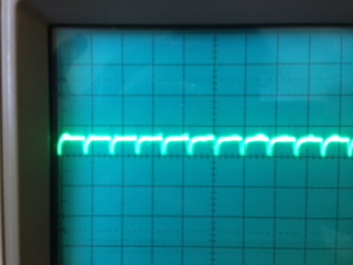
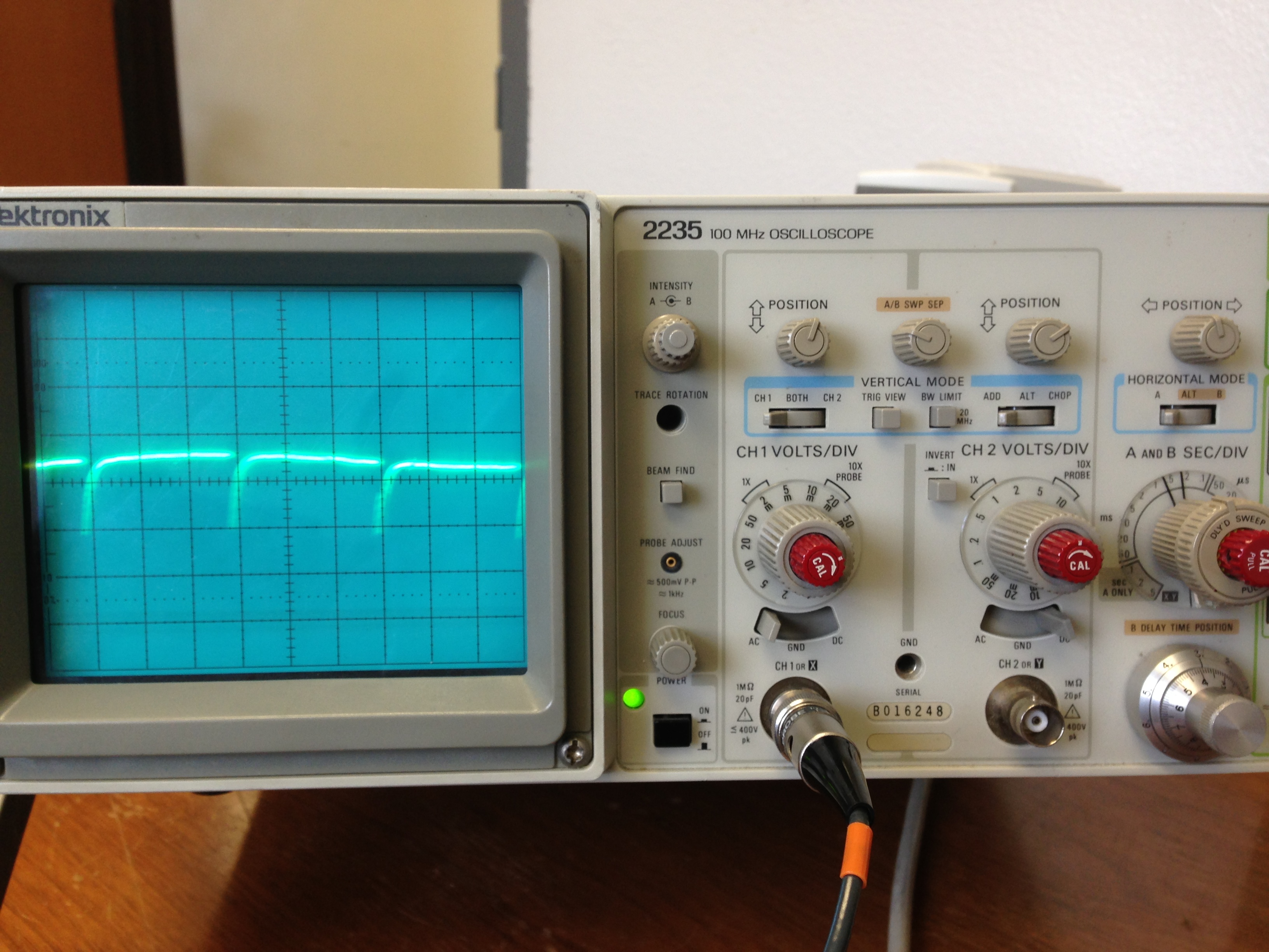
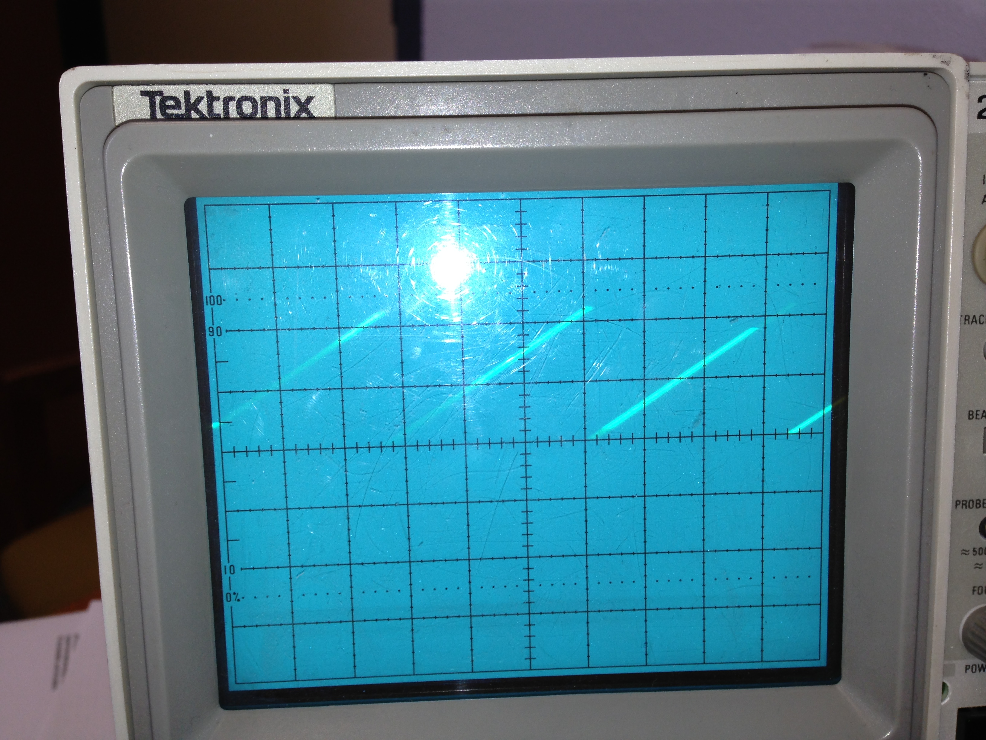
I would be happy if you please explain about the usage of 0x7FF value in the DAC register.For viewing the analog output I am using the Pin 6.0 and Pin7.6 in the target board pf MSP430F6638. Though I debugged and ran the project successfully I am unable to find the signal with a maximum amplitude in the oscilloscope.I would be happy if anyone could help me with this issue.

Thanks in Advance.

  • aishwarya karumanchi said:
    DAC12_0CTL0 |= DAC12ENC; // Enable DAC12

    With setting DAC12AMP, teh DAC is already active. DAC12ENC is only required if you use the advanced synchronization features, to synchronize the output change witha timer or with the other DAC.

    aishwarya karumanchi said:
    DAC12_0CTL0 = DAC12IR + DAC12SREF_1 + DAC12AMP_5 + DAC12CALON;

    DAC12CALON starts an internal calibration process. Before you can proceed, you'll have to wait until this bit clears itself again.

    aishwarya karumanchi said:
    please explain about the usage of 0x7FF value in the DAC register.

    DAC12SREF_1 picks VCC as reference. The DAC is a 12 bit DAC, so writing 0 to DAC12_0DAT results in 0V output and 0x0FFF results in VCC output.
    The values between linearly scale from 0V to VCC. So writing 0x7FF, which is about 1/2 of 0x0FFF, to DAC12_DAT results in an outpu tof 1/2Vcc (which is ~1.5V for Vcc=3V).

    Since you only write once to DAC12_0DAT, the output is static. For a waveform, you'll have to constantly change the value in DAC12_0DAT (here comes the timer synchronization into play).

  • Hello Jens,

    Thank you so much for your information which is very valuable.I tried changing the values for DAC12_DAT from 0x0000 to 0x0FFF for which i need to get around 0V and 3V  respectively.But i found that the amplitude range is from 0 to 0.03.Please suggest me how can I increase it and also reduce the noise of the signal.

    Moreover I found that I have AVcc of 2.7V (default) in the target board of MSP430F6638.It would be helpful if you also explain about the timer synchronization more in detail. 

    Thanks in advance.

  • Your MSP has DAC outputs on P6.6/6.7 and P7.6/7.7. Only one set is active. Maybe you check the wrong one and the amplitude you're measuring is just crosstalk on a floating pin. With the DACOPS bit clear, the output voltages appear on P6.6 for DAC0 and P6.7 for DAC1. If this bit is set, they appear on P7.6/7.7

    Also, the DAC maximum output current is limited. Currents above 1mA cause the output voltage to break down.On 1mA, the maximum output voltage is already limited to VCC-0.3V (or 0.3V, when sinking 1mA for an output of zero).

    aishwarya karumanchi said:
    It would be helpful if you also explain about the timer synchronization more in detail. 

    It is fully described in the users guide. YOu can use the PWM output signal of a time (see there) to move the previously written value in DAC12_DAT into the DAC output voltage generator. For both channels synchronously. So you can write the next output value whenever you want, and when the tiemr PWM cycle ends, the DAC will switch to the new setting rather than when you write to the register.

  • Thank you so much for your valuable information.I am actually using the PIn6.6 for DAC0 and connecting the other pin of oscilloscope to AVss of the target board MSP430F6638.I am attaching a image which shows my output on oscilloscope.

    Can you please see this and tell me how to remove the clippping of the signal of small of amplitude 0.07 only.Please do let me know your suggestions for improving the signal.

    Thanks in advance.

    g.

  • With the code you originally posted, you should see a straight flat line. Not more and not less.

    I have no immediate idea how the shown waveform could happen. However, I can construct a case:

    The output is shorted to GND by a standard diode (0.7V forward voltage). After some time the power supply shuts down due to the overcurrent and the MSP is reset. This would explain the clipping and the periodic drops in the signal.

    However, this scenario isn't a very likely one, just one that would give this waveform. Also, the maximum output current of the DAC isn't that much (only a few mA) and I guess the supply would have some headroom too.

  • Hello Jens,

    Thank you so much for your help and I appreciate your patience.Since I am new to this field please pardon my innocence.I am actually trying to form a saw tooth waveform as the output.I thought that the program which I am using gives output as some wave form.Could be please let me know the logic how I can modify the program to get the saw tooth output.
    Thanks in advance.


  • aishwarya karumanchi said:
    Could be please let me know the logic how I can modify the program to get the saw tooth output.


    (Very) simple sawtooth output would be...
    Output will increase in ~13mV steps (3.3V VCC as reference). You can smoothe this by an external low-pass filter (R/C combo), but this will also affect the falling edge of the output.

    unsigned char i = 0;
    while(1)
    {
      DAC12_0DAT = i<<4;
      i++;
    }

  • Hello Jens,

    Thank you so much for your help and patience.According to previous post I modified my code and it is as follows.

    #include <msp430f6638.h>
    unsigned char i = 0;
    void main(void)

    {

    WDTCTL = WDTPW + WDTHOLD; // Stop watchdog timer

    // AVcc is used as reference, calibration on, DAC on

    DAC12_0CTL0 = DAC12IR + DAC12SREF_1 + DAC12AMP_5 + DAC12CALON;
    DAC12_0CTL0 |= DAC12ENC; // Enable DAC12
    DAC12_0DAT = 0xFFF; // ~1.5

    while(1)
    {
    DAC12_0DAT = i<<4;
    i++;

    Please suggest me if I need to do any other modifications.I debugged and ran it.But the output is not in the form of a saw tooth waveform.According to your previous posts I learned that we need to enable the filter.Could you please explain me about this in detail.I am now using the Pin6.0 (3rd pin on the board)and pin7.7(7th pin on the target board).Please do let me know if I need to change any pin connections.I am also attaching an image of my output along with this.

    Please pardon my innocence if I am in lack of knowledge of even basic concepts.

    Thanks in advance.

    g a

  • You don't set DACOPS, so P6.6 (pin 3 of the chip,Are you sure you're probing the right pin?) is the pin on which the output appears. Or should appear.

    However, takign a closer look at your screenshot, it looks like you have a sine wave superimposed, which is a sign of problems with the GND reference.
    And as I said before, the 'pulsed' output seems to indicate that the device undergoes a cyclic reset.

  • Hello Jens,

    I am right now using the PIn3 for DAC0 and even tried for Pin4 on the target board by enabling DAC1.I am connecting the other pin to Avss. Could you please confirm me whether I am using the correct pins or not. 

    Thanks in advance and  appreciate your patience.

  • aishwarya karumanchi said:
    I am right now using the PIn3 for DAC0 and even tried for Pin4 on the target board by enabling DAC1

    Pin3 on the processor shoudl be DAC0 output. However, are you sure that Pin3 of the 'target board' is really connected to PIN3 of the chip?

  • Thank you for your suggestions.I got the sawtooth waveform  output which is as follows.


    I am using this code and could you please explain me this code.


    #include <msp430f6638.h>
    unsigned char i = 0;
    void main(void)

    {

    WDTCTL = WDTPW + WDTHOLD; // Stop watchdog timer

    // AVcc is used as reference, calibration on, DAC on

    DAC12_0CTL0 = DAC12IR + DAC12SREF_1 + DAC12AMP_5 + DAC12CALON;
    DAC12_0CTL0 |= DAC12ENC; // Enable DAC12
    //DAC12_0DAT = 0x7FF; // ~1.5

    while(1)
    {
    DAC12_0DAT = i<<4;
    i++;
    }
    }

    I am also in need of triangular wave.Could you please let me know the logic for that.

    Thank you so much for your patience.

    Please pardon my innocence.

  • The voltage at the output pin corresponds the the last value you wrote to DAC12_0DAT. When you change the value, the output changes accordingly. A value of 0 results in 0V output, a value of 0x0FFF results in reference output (Which is VCC in your case).
    The sawtooth code I outlined increments the value in ADC12_0DAT by 16 in each loop. After 255*16 it overflows to 0*16 (because I is a char and overflows from 255 to 0). Which gives the sawtooth form.
    The speed at which the sawtooth increases depends on the execution speed of the loop and the step size. For a precise timing, you can use a timer, use the timer ISR to update the values and synchronize the output update.

    For generating any waveform, you can create a table of 256 integers which holds the output values. Instead of putting i<<4 into the output register, you can assign table[i].
    You can use Excel to calculate the values required.

    E.g. for a sine wave, create th following document:

    A   | B                 | C
    -------------------------------
    0   | = A1*2*PI()/256   | = SIN(B1)*4095
    1   | = A2*2*PI()/256   | = SIN(B2)*4095
    ...
    255 | = A256*2*PI()/256 | = SIN(B256)*4095

    Column C then contains the values to put into the table. if you copy them to the DAC register, the output will form a fine sine wave. However, teh frequency still depends on the CPU speed.
    With a similar trick, you can create any kind of waveform. I use it in a project to generate a sine wave of up to 50kHz. However, I calculate the values inside the MSP  (and store them in a ram array) based on the requested frequency and amplitude. Then I output the precalculated data using DMA.

**Attention** This is a public forum