This thread has been locked.

If you have a related question, please click the "Ask a related question" button in the top right corner. The newly created question will be automatically linked to this question.

connection RF CC430F6137 vs. CC430F5137

Other Parts Discussed in Thread: CC430F5137, CC430F6137

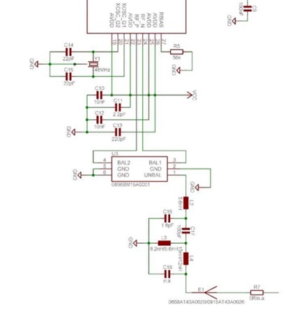
hello. I have problem with communications between CC430F6137 and CC430F5137. I have examples SLAA465 CCS5 Fixed_LT_FIFO.When I connected CC430F5137 with CC430F5137 all is OK. When i have connected CC430F6137 with CC430F5137 systems can't communicate. where is problem? Channels = 0x00, Adress=0x00, RfRegSetings.c files are all the same.

best regards Thomas

  • The 6137 has the additional LCD controller. Its default configuration might differ from teh 5137 and maybe your hardware setup doesn't proplerly initialize everything (especially port pins).

  • which? everything is the same

  • someone in this forum to know anything or not?!

  • Thomas,

    which hardware are you using? Are you using TI development kit such as EM430F6137 and EM430F5137 or your own custom board. I would suggest to try testing the devices using TI development kit.

    Have you tried to use SmartRF Studio? You can try to do basic packet testing with the boards.

  • I'm using examples SLAA465. I have 2 pieces of ewaluation kit Olimex - MSP430-CCRF.

    MSP430-CCRF via MSP430-CCRF - connection is good.

    I made 2 pieces PCB with CC430F6137 and i have good connection.

    When I have connection MPS430-CCRF wiht my PCB CC430F6137 I don't have connection. I don't have SmartRF.

    best regards

  • Thomas,

    because you are basically making your own custom board, i would suggest you to use the spectrum analyzer to see whether the signals have been transmitted at the right frequency. What i think the problem could be, is that the filter and balun part doesn't really comply with each other, and thus this will shift the transmitted/received frequency. On the same board, of couse because they have the same error, they can communicate with each other, while with different board which has different error, the communication will not work.

  • Tomorrow I will have the good oscilloscope. In my PCB quartz resonator is 26MHz +/-30ppm. Olimex PCB quartz is 26MHz +/-10ppm. Maybe this is problem?

  • Leo Hendrawan said:
    What i think the problem could be, is that the filter and balun part doesn't really comply with each other, and thus this will shift the transmitted/received frequency.

    Filter cannot *shift* transmitted frequency. Filter can only filter spectrum components, weaken signal in some band(s). Anyway this is good idea to check balun networks - are they tuned for same band? It could be that one board is tuned for 400MHz band but another - for 800MHz or just have improper balun components thus degrading performance.

    You shall try very close proximity transmission, also check & compare filter/balun L & C components using LRC meter.

    Thomas TMEA said:
    Tomorrow I will have the good oscilloscope.

    Then you better have Tektronic MDO4000. Plain scope is more or less useless for RF work.

    Thomas TMEA said:
    In my PCB quartz resonator is 26MHz +/-30ppm.

    CC-series radios are doing frequency offset compensation and certainly +/-30 ppm (26*30 Hz) shall be within compensation limits. You shall check FOCCFG register to ensure that compensator is not switched off. Other option - just try OOK modulation which is way more tolerant against carrier frequency shift.

  • Simple problem that many people run into is installing the wrong load capacitance on the crystal in their custom design. Having too low or too high of a load capacitance can shift the center frequency enough that two narrow band radios will not connect. That can be why two radio boards of the same design can connect, but two different board designs do not. Also many people are not aware that the load capacitors between the pins of a crystal and ground act as series capacitance across the pins. So they typically choose values that are too low. In a typical crystal circuit design with capacitor to ground on each pin, the value of the capacitors should be slightly less than 2 times the load capacitance specified for the crystal.

  • Timothy, Ilmars,

    thanks for correcting my wording. I am basically not an expert in RF hardware, but from my experience, this kind of problem occur just as Timothy explained, basically when trying to make custom board they basically made the same mistake on all boards, so that they can communicate with each other, but not with another board.

  • Sir,

    I have my own prototype model with cc430f6137 , i designed the layout with balun circuits (868 mhz).

    i procured em430f6137rf900 , in that board, they have designed cc430f6137 without a balun circuits(868 mhs)

    i have a working code for rf transmitting and  receiving , i am not able to transmit or receive.

    does this problem might be of balun circuits?

    regards

  • No BALUN circuit is no problem if you are using a balanced antenna. (BALUN stands for BALanced to UNbalanced). Attaching a standard unbalanced antenna (one side GND, other side signal) without a BALUN won’t work or worst case fry the output drivers.

    However, if everything is made correctly, both methods will emit/receive "compatible" radio waves. So for the receiver it is unimportant whether the sender uses a BALUN or not (and v.v.). Or what type of antenna is used on this or that side. Only frequency and modulation type are important. (and of course sending power and distance)

  • Hello Jens

    Thank you for your valuable explanation. It helps me a lot. Now i am able to transmit my signal from my own prototype board, but i am not able to receive, I also checked the frequency its 890mhz, actually the tuning circuit was for 868mhz, i attach my reference design here for rf section

    Regards

  • hello

     i can receive my signal in RF_P and RF_n with minimum amplitude .

    suggest me how to tune my circuit for amplitude pk-pk 1v. now i am getting pk-pk around 240mv

  • Well, I’m no RF expert.

    I see you’re using a BALUN chip, so why is there another network between the chip output and the antenna? I’m just asking.

    From my understanding, a pk-pk value of 250mV is quite large for an antenna input, unless there is some sort of amplification. 1V? Wow! Do you connect the sending output directly to your input?
    Or are you talking about output signal voltage swing? Well, it then depends on the selected sending power (voltage on chip output) and, of course, the BALUN fitting the sending frequency (voltage at antenna)

**Attention** This is a public forum