This thread has been locked.

If you have a related question, please click the "Ask a related question" button in the top right corner. The newly created question will be automatically linked to this question.

ADC stability for external temperature measurement

Other Parts Discussed in Thread: MSP430G2553

Hi,

I am using an external temperature probe (MCP9700-E/TO) and msp430g2553

And this code

  void checktemp(void)
  {
       ADC10CTL0 &= ~ENC;    // Disable ADC
           ADC10CTL0 = SREF_0 +SREF_1 + ADC10SHT_3 + REFON + ADC10ON  + ADC10IE;    //+REF2_5V// Use reference, 1v5 (2v5 disabled)
           // 16 clock ticks, internal reference on
           // ADC On, enable ADC interrupt, Internal = 'ref'
           ADC10CTL1 = ADC10SSEL_3 + INCH_6;    // Set chan6, SMCLK
       __delay_cycles (30);    // Delay to allow Ref to settle, was 20
           ADC10CTL0 |= ENC + ADC10SC; //enable and start conversion
  temp=(ADC10MEM);
              }

The code is over sampled 12 time per reading and is pretty stable with temperauture increasing/decreasing/remaining constant.  The probe also has decoupling caps on.

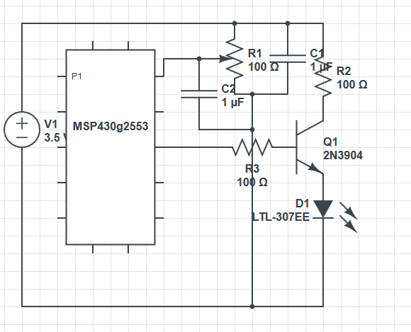
The problem comes when I switch an external heating element on/off with the msp430.  This is through a transistor, another transistor then an ssr.

Turning the output off causes the adc to decrease about 10 units, even with the over sampling.  This causes the output to oscillate on/off/on etc and also the temperature readout to fluctuate somewhat wildly.

Am I doing something wrong or is the internal reference going to be that unstable during switching?

  • Hi pitt,

    I suspect either noisy sensor or poor ground connection to the sensor.

    From temperature probe data sheet :

    it is recommended that a decoupling capacitor of 0.1 µF to 1 µF be used between the VDD
    and GND pins. In high-noise applications, connect the power supply voltage to the VDD pin using a 200Ω
    resistor with a 1 µF decoupling capacitor

    Peter

  • Didn't see the requirement for a resistor, will add and see if it improves the situation.  Else I'll be going to a one wire temp probe.

    I will report back,

  • The series resistor probably won't help much. Tis MSP has a combined supply pin for both, analog and digital supply. So changes in the supply voltage, caused either by MSP internal current changes or external ones, will slightly affect the reference voltage and therefore the conversion result.
    If you have this series resistor, the current ripple caused by the MSP will have bigger influence, while external ripple will have less. However, if the external load is constant (which it is in your case, until it is switched off again), it will cause a similarly constant change in the supply voltage regulation which will sooner or later (depending on R/C combo) arrive on the MSP side of the resistor too, so nothing gained.

    On MSPs with separate analog supply pins, a series resistor of 10 to 100 Ohms between digital and analog supply pin is a good thing, along woth a 10µF Tantalum/100nF ceramic combo. This will filter even the ripple caused by the digital part of the MSP itself. Also, routing the analog ground separately to the regulator GND pin also increases prerformance.
    But here again, the resistor on analog supply pin will only filter noise, not low-frequency changes of VCC.

    BTW: I'd recommend implementing a small hysteresis in software. :)

  • Added the resistor but no change.  I also tried different capacitors but no such look.  My code is basic at the moment just on/off so the problem could be solved in code.  I think only the immediate temp measurement after control input is unstable, thus pushing off the whole oversampled set of data.

    I am now switching to a one wire temperature probe as it has increased resolution and is in a proper package.  Any further problems will likely be solved in code.

    Thanks for your help guys.

  • pitt the younger said:
    This is through a transistor, another transistor

    Could you show schematics?

  • Sorry, its on the breadboard only.  I have simplified the circuit with just a transistor and an led on the output (with resistors) and still the same problem.

    This is a rough layout but numbers of components and values are changed (and r1 is the fancy thermistor thing)

  • Is the heater powered by the same power supply as the MSP?

    If so, does the voltage drop when the heater is on?

  • The heater is currently on a different power supply so no voltage drop.

    When using the led the sensor voltage is only unstable briefly after switching.  In either the on or off state the output is consistant

  • R3 value is unnecessarily small. If VCC supply is weak enough, it can be source of your problems. Try R3 increasing to 1k or so. Do not forget about decoupling capacitor(s) between VCC and GND as close to uC as possible.

    100ohms of R1 also is just waste of the power. You can use 10k here.

  • The contact resistant of a Breadboard is quiet high.

    Create a separate Analogue ground on your Breadboard connected separated from digital signals directly to the MCU (solder a second Vss leg to the MCU) and also create here a new AVcc.

  • Yep, a separte analog gnd routing is always a good idea if analog precision is required. Many MSPs have dedicated AVss and AVcc pins for this reason.
    As any current on the GDN traces changes the GND level. And any current change causes GND ripple.

**Attention** This is a public forum