This thread has been locked.

If you have a related question, please click the "Ask a related question" button in the top right corner. The newly created question will be automatically linked to this question.

Constant DC current (source or sink) using MSP 430 op amps

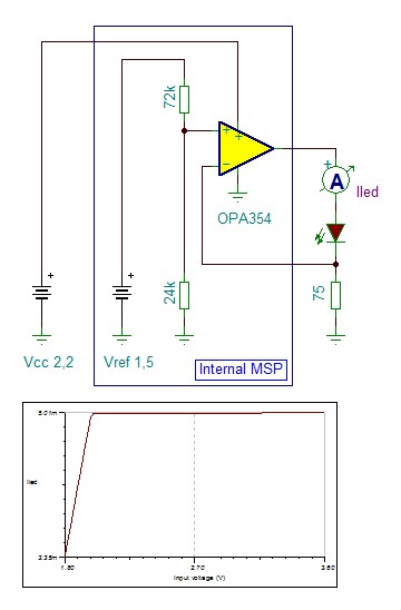
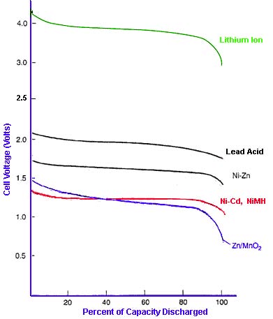
I am building a very simple MSP 430-based controller, and I need a single output to drive the LED in a solid state relay. To make it work over a range of discharging battery voltages (3.3v and lower), I thought a constant current output (10 ma or less) would be appropriate. I'm a software guy, so I have very little analog hardware expertise, but I seem to remember that one can make a constant current driver with an op amp or two. To keep the part count low, I'd like to use the op amp(s) in an MSP 430.

Questions:

Can this be done? If so, how?

What MSP 430 do I need? The controller is so simple, the smallest one with the right op amps is probably adequate.

Is there a better way?

This is probably not the first time this has been asked, but I haven't been able to find the answer. A link to an existing answer would be good, or just answer here.

Thanks.

  • Bazerko Bob said:
    (3.3v and lower)

    You shall define range here. Because 0.01V is lower than 3.3V too.

    If it is slow relay-style on/off application, then consider just LED boost driver with PWM/dimming input. Something like CAT32 from OnSemi or similar.

  • Bazerko Bob said:
    I thought a constant current output (10 ma or less) would be appropriate.

    I don't think that any of teh OpAmps available in an MSP allows for 10mA output current. Remember the MSP is low-power and high-current OpAmps usually aren't used in low-power applications.
    However, only a few MSPs have general-purpose OpAmps (most that have OpAmps have them tied to the ADC input, but the majority has none at all, as OpAmps aren't really low-power devices)

    So I sugges tpickign the cheapes MSP that can do th ejob and use an external OpAmp that is suited for your applicaiton.

  • I was afraid of that (the current limitation). The LED driver above sounds like it will do the job. Thanks to both of you.

  • What you could try (depending on the voltage range and the SSR/LED you are using); Measure the voltage and calculate the Duty cycle for a PWM to the LED. PWM frequency about 1Khz, and if available you can use 2 or more Port output pins in parallel (max each aprox 5mA).

  • Bazerko Bob said:
    Is there a better way?

    For this I would use 3bit DAC. 3 ports feeding  200,400,800  ohm resistors connected to the SSR.

    Then measure the battery voltage (ADC10) and set a suitable outputs. In this setup you should use the "open collector" output driving style.

    Peter 

  • Is a good solution. But how to set output driver to ‘Open Collector’ style? The only way I see is to switch between Input/Output mode.

  • I like this offer either. Do you know SSR type? Checking VI curve of it's LED perhaps will tell how you shall drive it. Maybe just two different drive strenghts is enough. BTW You did not mention planned VCC range of msp430! Is it 3.3V .. 2.2V ?

  • Leo Bosch said:
     how to set output driver to ‘Open Collector’ style? The only way I see is to switch between Input/Output mode.

    Yes that is how.

  • Thanks to everyone. You suggested two important concepts that I should have thought of, but didn't. First, the current doesn't need to be exact, only close enough. Second, the MSP 430 can measure its Vcc and select the resistor value to use to get the desired current. Combining these ideas, I came up with this:

    The SSR minimum LED current is 3 ma, typical is 5 ma, so I chose resistors to provide 4 ma or more. The voltage drop across the LED is typically 1.5 v, so when Vcc goes from 3.3 to 2.2 volts as the battery discharges, the voltage across the resistor goes from 1.8 to 0.7. To get 4 ma when Vcc is 2.2v, the resistor is 180 ohms. This would be adequate by itself, but at 3.3v the current would be 10 ma.

    So here's my plan: Connect each of three MSP outputs through resistors of 180, 240, and 360 ohms. To turn on the LED, enable one of the outputs and tristate the other two. This means from 3.3 to 3.0 v, the current is 5 to 4 ma. From 3.0 v to 2.5 v, the current is 6 to 4 ma. From 2.5 to 2.2v, the current is 5.5 to 4 ma.

    One final question: will this work?

    I wanted to find values of R1 and R2 so that turning on both would provide the right current for the lowest voltage range. This would save me an output pin, but I couldn't make the numbers work. Maybe they don't exist.

    The original question was about a PIR controller, but I am going to use it in a motion-activated camera shutter release. I'll put it where I expect a butterfly to appear and wait until I get the picture I want or until the battery runs out. If it works, I'll post photos somewhere, but don't hold your breath. I expect there will be a long wait involved.

  • My previous post describes a DC solution with different voltages, simulating a DAC with three output pins. I'll research the characteristics of the SSR and if possible, try the PWM idea also. Thanks.

  • If you do like the internal Op-Amps (which I do also) and the current does not exceed 5mA, you can also consider this setup;

  • Bazerko Bob said:
    One final question: will this work?

    The SSR drive will work, but the PIR butterfly detector not likely. 

    Peter

  • I'm not sure how serious you intended to be, but the PID (not PIR, my mistake) controller and butterfly detector are two different projects, having only in common the SSR actuator. The butterfly detector uses an ultrasonic detector and the MSP 430 will control it and trigger the camera when the butterfly is at the same distance as the camera is focused.

    thanks also for the op amp solution. I'll have to find a MSP430 that has one.

  • Bazerko Bob said:
    I'll have to find a MSP430 that has one.

    The following devices has Op-Amp’s: MSP430x22x4, MSP430FG42x0, MSP430FG43x, MSP430xG461x and MSP430FG47x.

  • Actually I disagree about even thinking of battery discharge for "butterfly hunting device" - your photo camera will discharge much, much, much sooner than typical AA or AAA alkaline battery set powering msp430 and PIR sensor.

    Driving SSD LED from high precision current source is gigantic overkill. First you are wasting money by paying for opamp and secondly you are limiting your microcontroller choice.

  • If it's not likely that it will work, I won't bother building one, but you don't say why. What is your expertise in photography? In butterflies? Can you explain your pessimism?

  • Bazerko Bob said:
    What is your expertise in photography? In butterflies?

    I know nothing about butterflies but is it so important when we are talking about constant current drive of SSR? Oh, and I know enough about photography to understand that your photocamera shall be powered on while waiting for butterfly.

    Bazerko Bob said:
    Can you explain your pessimism?

    My pessimism here is - you don't have to bother about constant current drive for SSR if you have more or less constant battery voltage which you will have for sure if you use AAA or AA batteries instead of button cell.

  • Ilmars said:
    you have more or less constant battery voltage which you will have for sure if you use AAA or AA batteries instead of button cell.

    Strongly disagree!

  • I think we all agree the SSR driver will work. There is disagreement whether saving a  little current is worth the trouble.That's not what I'm asking about.

    Peter Dvorak said the butterfly detector will not likely work. My question is "Why not?"

  • My comment was based on PIR detector used for butterfly detection.

    The PIR needs a temperature difference moving across the sensor field.

    Since butterflies are not warm blooded, the calibration will be tricky.

    Peter.

  • Leo Bosch said:

    you have more or less constant battery voltage which you will have for sure if you use AAA or AA batteries instead of button cell.

    Strongly disagree!

    [/quote]

    LOL :D Of course batteries discharge. Main question is: how fast you discharge them, when (at which voltage) you treat them as discharged. If you look at discharge graph, alkaline have "more or less constant" voltage down to 80% discharge. NiMh rechargeable have even better discharge results.

    Low power PIR sensor can operate for months from two AA batteries. Instead of trying to implement constant current LED driver using __built__in__ opamps to squeeze out last 10% of battery charge I would rather implement "low battery" indicator. In case I really need constant current drive of 0..20mA LED then I would go either 1) three AA alkaline/nimh batteries and 3V linear regulator 2) boost 3V switching regulator.

  • Peter Dvorak said:
    The PIR needs a temperature difference moving across the sensor field.

    Yes. If your moving target have the same temperature as background - then you have problem. BUT if background is shadow part of scene and butterfly will be illuminated by sun - it will work. Also opposite combination possibly will work, but doubt you want to get pictures with blown-away highlights in the background.

    Did you consider IR distance sensors?

  • My mistake. "PIR" was a typo. I meant "PID" and that was for a different project. The butterfly detector is based on an Ultrasonic Range Finder. My butterfly expert tells me the butterflies can't hear the sound. I hope she's right.

    If this works, I'm finished with the electronic part and out into the field. If not, I'll look into some infrared technologies.

    Thanks, all.

  • If you want to use light; Insects are less sensitive for orange-red light, but to catch them use light surround 380nm.

**Attention** This is a public forum