This thread has been locked.

If you have a related question, please click the "Ask a related question" button in the top right corner. The newly created question will be automatically linked to this question.

CC430F5137 and MEMS

Other Parts Discussed in Thread: CC430F5137

hi,

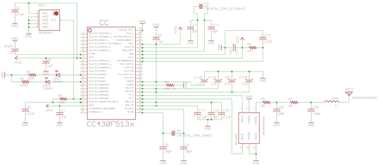
I'm trying to connect an MEMS microphone (ADMP401) with the CC430F5137, and its must has the smallest size and fewest number of components possible, so I tried follow some schematics, but I don't know if it's correct and I cant try build it any times I want because the laboratory I'm using is busy almost always, so can somebody give me one ok or one wtf?
  • Well, your circuit depends on what oyu want to do with the MEMS microphone.

    Currently, you have attached it to a digital I/O pin. So the pin input will flip when the signal crosses a certain (undetermined!) level. With a hysteresis for falling back.

    If you connect the signal to P2.0/2.1or 2.2, you can use the ADC12 for determining the exact voltage. Or you use the comparator to get an interrupt.

    So to judge whether your schematics will do, you should tell what it shall do - in detail. With the schematics alone, I can just tell you that it will surely be okay for something. But not necessarily for your purpose.

  • I knew I connected to a digital I/O pin, I did this because I also didnt know where and how to use the ADC12 in this IC.

    Is hard to explain the application with few words, so is better I tell just I also pretend to use just like a normal microphone.

  • Paulo Cunha1 said:
    Is hard to explain the application with few words

    Then try with a few more. It's hard to give advice if the whole situation isn't known.

**Attention** This is a public forum