I'm having a frustrating issue with the MSP430FF5522 and I've isolated the problem to, what I believe, two DMA's working in tandem to unload data from an external radio chip, the nRF24L01+. I'll paste my code at the bottom, but here is some background and symptoms.
My device has the above mentioned radio chip connected via UCSIA1 configured as SPI. When this radio receives a packet, its IRQ pin goes low an an interrupt is called to unload the data into a buffer. I have two separate types of methods to do this. They both do virtually identical things (sending a series of bytes and moving the received bytes into my buffer). One method uses two DMA's to send and receive data, and the other method uses the code execution to do this. These are "NRF_Read_Payload_Via_DMA(BYTE *ptrBuffer)" and "NRF_Read_Payload_Via_CPU(BYTE *ptrBuffer)", respectively. Using the CPU method works fine, but it eats up extra clock cycles, which is an issue. The DMA method works for a while, but the output data will randomly go haywire after a seemingly random period of time (1-10 minutes).
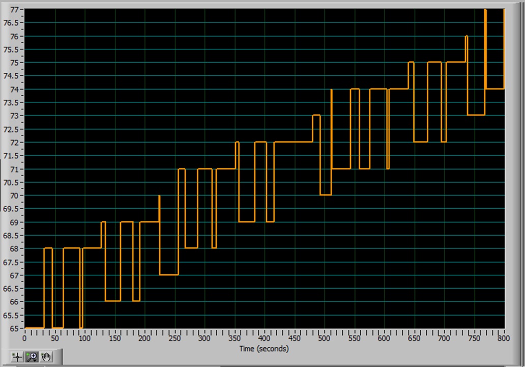
Once the data has been unloaded from the radio, it is sent to my PC via USB and presented in my LabVIEW program. Right now, I am sending test data to aid in solving this issue. Each "packet" that is received and unloaded from the radio chip is 32 bytes long, with all 32 bytes being the same value for that packet. The next packet will be the same thing, but all values incremented. This is repeated 102 times, then the cycle repeats. In other words, the first packet is a series of 1's, the next is 32 all 2's, the next 3, and so on with the last packet being a series of 102's. The result should be a stair step pattern as shown in the picture attached. This works fine for the CPU method and for the DMA for a few minutes...
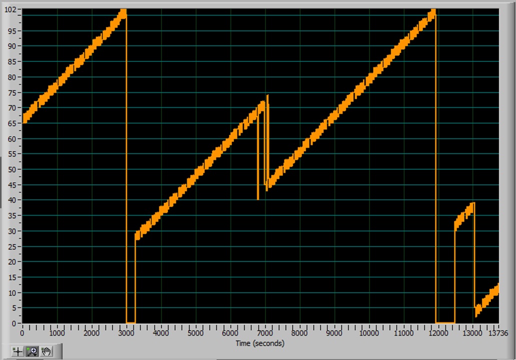
When the DMA method starts going nuts, it looks like the 2nd picture attached. There appears to be a pattern to the data, but I can't make sense of it or derive any clues from it. My SPI signaling is well within the radio chip's spec, so, I know the issue is on the MSP430's end and has something to do with the DMA... I just don't know what. Below are the relevant bits of code. If you really think the answer lies somewhere else, I can post more code. Also, disregard the incorrect X-axis labeling on my graphs. It should not be seconds, but individual bytes in each payload.
void NRF_Read_Payload_Via_DMA(BYTE *ptrBuffer)
{
	// We are going to assume the proper check has been made and that there IS, indeed, data in the FIFO to read
	// Chip Select Low to begin SPI communication
	CSN_LOW();
	// Update the address of the buffer to put received data into
	__data16_write_addr((unsigned short) &DMA0DA,(unsigned long) ptrBuffer);
	SPI_SendByte(R_RX_PAYLOAD);
	//Use DMA0 and DMA1 in tandem to read out Payload data
	DMA0CTL |= DMAEN;             // DMA0 Enable
	DMA1CTL |= DMAEN;             // DMA1 Enable
	DMA1CTL |= DMAREQ;		// DMA1 Start
	//A brief delay so the SPI byte that was read has time to show up in the buffer array
	__delay_cycles(24);     // ~1us @ 24MHz clock

	// DMA transfer in progress...
	// ...
	// ...
	while(DMA1CTL & DMAEN);		// Wait until DMA's are finished transfering
	//wait until last byte is finished RX'ing
	while( (UCxSTAT & 0x01));			// wait until the USCI is not busy
	//Old way of reading out Payload... VERY slow...
//	for(i = 0; i < 32; i++)
//		*payload++ = SPI_SendByte(NRF_NOP);
	CSN_HIGH();
}

void NRF_Read_Payload_Via_CPU(BYTE *ptrBuffer)
{
	CSN_LOW();
	SPI_SendByte(R_RX_PAYLOAD);		// Send the first control byte requesting RX FIFO data
	BYTE i = 0;
	//Old way of reading out Payload... VERY slow...
	for(i = 0; i < 32; i++)
		*ptrBuffer++ = SPI_SendByte(NRF_NOP);
	//wait until last byte is finished TX'ing
	while(!(UCxIFG&UCTXIFG));
	CSN_HIGH();
}

// Set up the DMA's for tag-teaming the data transfer to/from the radio.
// DMA0 is triggered when a byte is received, while DMA1 is triggered immediately after
// that, due to priority differences. DMA1 will then send a byte to the radio, causing DMA0
// to trigger again once the operation completes. This is repeated until all 32 bytes are done.
// DMA_Setup_Channel() takes the DMA_Data structure and fills in the required info. Nothing special.
void Setup_DMA_RX()
{
	struct DMA_Setup_Info DMA_Data;
	//Setup DMA Channel 0 for loading data into the radio
	DMA_Data.Channel 		= 0;
	DMA_Data.Trigger		= DMA0TSEL_20;					// Trigger when USCIA1 has received a byte
	DMA_Data.pSrcAddress	= (unsigned long *)&UCA1RXBUF;
	DMA_Data.pDstAddress	= (unsigned long *)Payload;
	DMA_Data.TransferSize	= 32;
	DMA_Data.ControlBits	= DMADT_0+DMADSTINCR_3+DMASBDB;
	DMA_Setup_Channel(&DMA_Data);

	// Setup DMA Channel 1 for loading config data into the ADC (SPI bus)
	DMA_Data.Channel 		= 1;
	DMA_Data.Trigger		= DMA1TSEL_21;					// Trigger when USCIA1 has sent a byte
	DMA_Data.pSrcAddress	= (unsigned long *)&DummyByte;
	DMA_Data.pDstAddress	= (unsigned long *)&UCA1TXBUF;
	DMA_Data.TransferSize	= 32;
	DMA_Data.ControlBits	= DMADT_0+DMASRCINCR_0+DMASBDB+DMALEVEL;//+DMALEVEL;
	DMA_Setup_Channel(&DMA_Data);
}
Good Data from CPU Method:

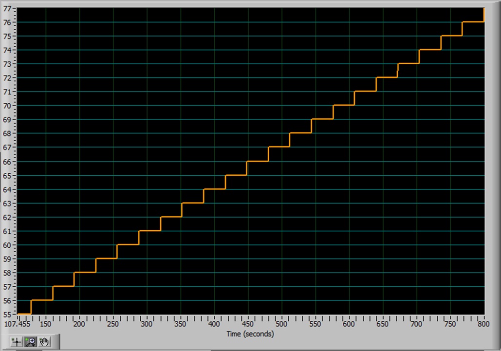
Zoomed Version of Good Data (CPU)
Bad Data from DMA Method
Bad Data (Zoomed) from DMA Method