This thread has been locked.

If you have a related question, please click the "Ask a related question" button in the top right corner. The newly created question will be automatically linked to this question.

msp430F1612 dac12

Other Parts Discussed in Thread: MSP430F1612

Hello,

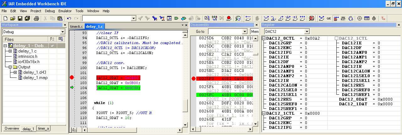
For MSP430F1612, for DAC12 I cannot enter the value in DAC12_0DAT. Below is the code and also the screenshot of IAR. As you see, no data loaded in DAC12_0DAT, neither voltage on P6.6/DAC0 processor pin. 

Any idea for fixing this?

  //dis GIE
  __bic_SR_register(GIE);
 
   //init P2.2 LOW
    P2IES &= ~P2IES_5; //dis int P2.5
    P2IFG &= ~P2IFG_5; //reset P2.5 int flag
    P2SEL &= ~P2SEL_5; //P2.5 IO
    P2DIR |= P2DIR_5; //P2.5 OUT
    P2OUT &= ~P2OUT_5; //OUT Low
  
   //Voltage reference ADC12, DAC12
    ADC12CTL0 |= REFON; //en VREF
    ADC12CTL0 &= ~REF2_5V; //VREF=2.5V
 
    //init P6.6 DAC12_0
    P6SEL |= P6SEL_6;
    P6DIR |= P6DIR_6;
    P6OUT |= P6OUT_6;
   
    //DAC12 settings
    //conv. DIS when DAC12LSELx > 0
    DAC12_0CTL &= ~DAC12ENC;  
    //dis INT
    DAC12_0CTL &= ~DAC12IE;
    //ungroup DAC12x
    DAC12_0CTL &= ~DAC12GRP;
    //ref: VREF+
    DAC12_0CTL &= ~DAC12SREF1;
    DAC12_0CTL &= ~DAC12SREF0;
    //12-bit res
    DAC12_0CTL &= ~DAC12RES;
    //conv. starts if DAC12ENC
    DAC12_0CTL &= ~DAC12LSEL0;
    DAC12_0CTL &= ~DAC12LSEL1;
    //DAC12 full-scale output = 3x reference voltage
    DAC12_0CTL |= DAC12IR;     
    //High speed & DAC12_0 OUT. P6.6 selected aotomatically for DAC12_0 out
    DAC12_0CTL = DAC12AMP0 + DAC12AMP2;
    DAC12_0CTL &= ~DAC12AMP1;
    //data IN: straight binary
    DAC12_0CTL &= ~DAC12DF;
    //clear IF
    DAC12_0CTL &= ~DAC12IFG;
    //DAC12 calibration. Must be completed BEFORE DAC12 use
    //DAC12_0CTL |= DAC12CALON;
    DAC12_0CTL &= ~DAC12CALON;
   
    //DAC12 conv.
    DAC12_0CTL |= DAC12ENC;
   
    DAC12_0DAT = 0x0A00;
    DAC12_0DAT = 0x0B00;
    DAC12_0DAT = 0x0C00;

  • I don't know why teh registers don't show a value, but it is likely just a screen update bug.

    however, your code has some flaws.

    You set DAC12IR, bu twith the next isntruciton, you implicitely clear it again. Also, while DAC12LSEL is 0, DAC12ENC is a doN't care - you don't need to set it nor does it serve any purpose.

    Also, all the bit clearing is superfluous. The default value is 0 anyway, and wiht the first "=" assignment, you clear all bits anyway which aren't set in the assignment.

  • Thanks for your time, Jens-Michael.

    The registers are not updated as it should be either as I bug I did at one or several points, I guess, or it is a bug in IAR IDE. How can you explain that other resisters are updated correctly, and only DAC12_0DAT is not updated correctly? The images blow are the proof.

    We are all learning from every mistake/bug. If you want, I can send you more screenshots.

    According to TI MSP430 User Man, DAC12IR should set Input Range. Following this instruction, I set In Amp Gain, which should not be conflictual with input range; it should affect the slow rate only,  which is another story.

    I agree that some instructions are redundant in effect. I put them them just hoping that it will work, which is not the case. Definitely, the bug is hidden somewhere. For sure I keep working on this until I'll find the bug and also I will post the result for helping others.

    Below you have some screenshots with notes. If you have other suggestions, please tell me.

    Best regards,

    Nicolae

  • Nicolae Miron said:
    Following this instruction, I set In Amp Gain, which should not be conflictual with input range; it should affect the slow rate only,  which is another story.

    The bits are independent, yes, but you raccess of the register isn't.

    DAC12_0CTL |= DAC12IR;     
    DAC12_0CTL = DAC12AMP0 + DAC12AMP2;

    The second instruction writes DAC12AMP0 and DAC12AMP2 bits to the register and clears all others, including DAC12IR. You simply omitted the "|" in the assignment.

    I never had any problem swith the DAC on the 1611. In fact I'm using it heavily.So I guess it is a display problem in the debugger. Can you try a manual refresh of the register view?  Since fetching data through JTAG is very slow, the debugger doesn't update everythign at every step. I agree that it shoudl do so here, but I don' tknow th ealgorithm with which it determines whether to update or not.

    Personally, I don't use any debugger. While it is convenient to debug functions, it often causes more problems than it solves when it comes to interactions with peripheral modules, realtime events and parallel execution (interrupts/threads).
    I don't even have one installed. (no CCS/IAR, just plain MSPGCC compiler). If I want to know a value at a certain point, I output it thorugh serial or let LEDs blink or use PWM signals (yes, you can send a 16 bit value through PWM to an external counter). All of this doesn't affect the realtime program behaviour.
    But well, I learned coding in times where there was no IDE at all, and programs were written to the processor byte by byte with some switches and a pushbutton. :)

  • Thanks Jens-Michael,

    Your hint worked for me.

    I had also another bug in my code:

    volatile unsigned short DAC12_0DAT;

    not used, which prevented to see DAC12_0DAT updated. I removed the declaration and now is OK.

    I totally agree with you for using additional means for checking the code execution. Typically,  for sync purposes, I toggle a digital output for testing small pieces of code.  I make small timing loops to see with oscilloscope dynamically what it is happening. I have this habit since the old days you are talking about.

**Attention** This is a public forum