This thread has been locked.

If you have a related question, please click the "Ask a related question" button in the top right corner. The newly created question will be automatically linked to this question.

Light switch controller power using MSP430

Other Parts Discussed in Thread: TPS63030

Good day!

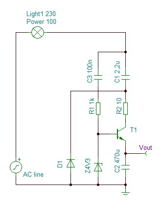
I have the task to build smart light switch. Is there any reference design for powering up the MSP430 board from power line like on the picture below? The key problem is there is no zero power line, just the ligt switch breaking the hot power line going to light bulb. Of course, then light is off, it is very easy to get power by consuming small current thru the bulb. But this controller also should work then light is on.

  • sorry, image does not load... 

  • When the light is on, you can get some voltage over a shunt resistor, followed by a buck/boost converter (to compensate for different operating current.
    It might also be possible to have a voltage drop over your switch (depending on switch type) that is sufficient for a buck/boost converter.
    The tricky part is that in off state, you have full power line voltage while in on mode, you only have a small voltage. And the buck/boost has to cope with both.

    A possible way is to combine both methods: use two rectifiers to combine the voltage over the shunt (when lights on) with the (divided by resistors or other means) full line voltage that appears over your switch then the light is off.

  • Most "intelligent" retrofit light controllers uses simple trick: they never open thyristor for full AC mains half-period. You lose 0.1% of illumination or even less - nobody will notice anyway, but this is sufficient to power controlling circuit.

  • The problem is, for the possible max power of light source of 200W, the current will be about 1A, so to get 4V for power supply I should use 4Ohm shunt, which will give 4W of power dissipaton on shunt, which is not acceptable.

    as for light off situation the things are much more simple - i can use 220K and 5K resistors in series, setting the load in parallel to 5K resistor.

  • Look for Microchip AN958 and you will see what you are looking for. [edit] Sorry, this is not right one. Oh crap - I can't find it anymore.. Sorry.

  • Look to the schematic I drawed - http://clip2net.com/s/5Rxl4a

    Will it work? 

    With TPS63030 it should provide 3V output, right?

     , sorry, but this approach will not work as the light switch can also be switched manually - e.g. the board connected in parallel to regular light switch.

  • Oleg Kobrin said:
    Look to the schematic I drawed - http://clip2net.com/s/5Rxl4a

    You need some zener. Because surges can happen.

    Oleg Kobrin said:
    this approach will not work as the light switch can also be switched manually - e.g. the board connected in parallel to switch

    I do not see any problems here - while manual switch is on then your board does not need to do anything anyway, so it does not need power.

  • Yes, I see. BTW, shunt cannot be used at all, as the power rates of lamps is very different, starting from 10W for LED lamps up to 200W for tunsten lamps. So we need to find the triac solution.

  • Oleg Kobrin said:
    the current will be about 1A, so to get 4V for power supply I should use 4Ohm shunt, which will give 4W of power dissipaton on shunt, which is not acceptable.

    Two mistakes: 1) 200W means rated current of 1A. Peak current (and therefore peak voltatge on the shunt) is SQRT(2) higher. You can charge a capacitor at this point. 2) my suggestion of a buck/boost regulator means you can use a shunt voltage of 1V or less, as well as significantly higher voltages.
    But you have to dimension the shunt voltage so that it is high enough even if you do not have 200W load.

    Instead of a shunt, you may use a high-current diode. It provides a voltage drop of roughly 0.7V (pick a proper one) independently of the current. With a good boost regulator, this will be enough for your supply. Of course you then cannot use the joining method using a bridge rectifier.

    However, the idea of never going to 100% duty cycle, so you always have a fraction of a wave to sufficiently charge a capacitor, is sweet.

  • You can try something like this;

  • Leo Bosch said:
    You can try something like this;

    And please don't kill yourself. Use 12V isolated transformer and 12V lightbulb for prototyping/development. When done - it's not that hard to size your circuit components from 12V to 110V or 220V.

  • Please explain, is this design will make lamp to light? Which is duty cycle? Which is power dissipation here? Which transistor is used? Will this work on lamps from 10W to 200W? How to switch off the lamp, continuing to power the scheme?

    Thank you!

  • The original question is How to power-up the MSP430. This is an answer, but for the power source only. Al other you have to calculate/add yourself.

    Oleg Kobrin said:
    is this design will make lamp to light?

    To light-up the lamp you have to add a Triac or SCR.

    Oleg Kobrin said:
    Which is duty cycle?

    The Duty-cycle is defined by your software in the MSP.

    Oleg Kobrin said:
    Which is power dissipation here?

    The Power-dissipation you have to measure or calculate and depends on the 3.3V load (MSP etc).

    Oleg Kobrin said:
    Which transistor is used?

    The transistor can be small 1A, Vce >= 300V, also the capacitors should be >= 300VAC.

    Oleg Kobrin said:
    Will this work on lamps from 10W to 200W?

    Certainly with 200W, the minimum depends on the Triac (minimal AK current).

    Oleg Kobrin said:
    How to switch off the lamp

    Automatically every 10mS (at 50Hz).


  • So, it is not what I need. I need to power up my device when the lamp is ON.

  • If you add a delay of 1mS prior to fire the Triac every 10mS you get after 250mS enough power to Power-Up your MSP (3.4V @ 1mA). If you need less power you can short the 1mS. In the main time your lamp is On.

  • Ok I understand the theory, but what is the schematics?

    remember, I need my MSP430 to swich the light on and off being powered up all the time as it also has some RF connectivity.

    so, I'll use a triac to controll the line, switching it off then i need to switch off the light and switching to 250/240 duty cycle to switch light on.

  • Oleg Kobrin said:
    So, it is not what I need. I need to power up my device when the lamp is ON.

    When using a triac to switch the lamp, the TRIAC will switch the lamp off on the next zero-crossing (of the current, not of the voltage, so beware for inductive or capacitive loads). At this point, you may charge a capacitor to provide supply for the next half-wave. Should be done almost instantly, then switch the triac on again.
    If you have a zero-crossing detection unit, the time it takes to detect the zero-crossing signal, checking whether the TRIAC needs to be triggered (lamp shall be on) and triggerign the TRIAC, should be enough to charge the cap.

    When you bridge the circuit with a mechanical bypass switch, you will of course lose your power supply. However, you don't need it as the switch overrides your operation anyway. Once the mechanical switch goes off, you have charge for your supply again, the MSP starts up and is operational again with the next zero-crossing.

  • Oleg Kobrin said:
    Ok I understand the theory, but what is the schematics?

    Do you need us to draw PCB layout too? Then develop software, care about manufacturing, marketing and sales activities? :)) [kidding]

  • Oleg Kobrin said:
    I need my MSP430 to swich the light on and off being powered up all the time as it also has some RF connectivity.

    Ah, a new requirement.
    I wrote my last reply before seeing this (the disadvantage of preloading pages for performance reasons)

    Oleg Kobrin said:
    so, I'll use a triac to controll the line, switching it off then i need to switch off the light and switching to 250/240 duty cycle to switch light on.

    That's probably the best way. But...

    If you need the MSP powered when the lamp is switched on by the manual bypass switch you mentioned, then you're hosed. If the lamp is on by a switch, you don't have any voltage drop where oyu could get your supply from - except for the said shunt (with all its disadvantages).

**Attention** This is a public forum