Hi
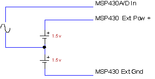
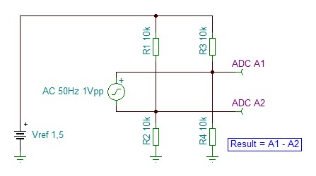
How to measure AC signal using ADC10 without using any external components for level shifting the signal.
The range of measurement is 1.0Volt ac peak to peak.
Thanks,
Prasadd Aritakula
Hi
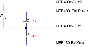
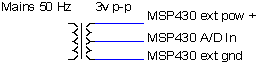
How to measure AC signal using ADC10 without using any external components for level shifting the signal.
The range of measurement is 1.0Volt ac peak to peak.
Thanks,
Prasadd Aritakula
**Attention** This is a public forum