This thread has been locked.

If you have a related question, please click the "Ask a related question" button in the top right corner. The newly created question will be automatically linked to this question.

How to start MSP430F2274 BSL via UART?

Other Parts Discussed in Thread: MSP430F2274

Hello my friends.

First, sorry for my bad english.

I'm using a CubieBoard2 ( http://cubieboard.org/2013/06/19/cubieboard2-is-here/ ) with Cubian ( a linux distribuition bases on Debian for cubieboard2, Cubieboard + Debian = Cubian) and a MSP430F2274 ( http://www.ti.com/product/msp430f2274 ), DA package, in another board.

The serial communication between the both boards is working fine. Just connect the required pins (TX, RX, VCC and GND) from MSP board to CubieBoard2 pins, connecting at 9600 bauds, 8 data bits, no parity and 1 stop bit.

I need to start the MSP BSL to upload a new firmware from Cubieboard2 to MSP430F2274, using the same UART.

I'd connected also the RST pin (pin 1) and TEST pin (pin 7) of MSP to another 2 pins into cubieboard2.

I wrote a C++ program (for cubie) for use these 2 pins of cubieboard to try to reset the MSP for start the BSL program, following the slau319g.pdf document, but I had no success.


I downloaded the slau319g.zip file also, but I saw another sequence for reset the MSP that I saw in the slau319g.pdf.

The program I made, opens the UART port using 9600 bauds, 8 data bits, even parity and 1 stop bit.

Following the slau319g.pdf, the sequence (item 1.3.1) is:

1 - Set RST and TEST to low (zero).

2 - Do some delay (I did 1ms).

3 - Set TEST to high (one), making the first positive transition.

4 - Do some delay (I did 1ms).

5 - Set TEST to low (one).

6 - Do some delay (I did 1ms).

7 - Set TEST to high (one), making the second positive transition.

8 - Do some delay (I did 1ms).

9 - Set RST to high (one).

10 - Do some delay (I did 1ms).

11 - Set TEST to low (zero).

After it, I did a 3 ms delay and sent a byte 0x80 via UART, but I got no response (byte 0x90 would expected).

Following the sequence describe above, I can reset the MSP, but just the user program starts, not the BSL program.

When I downloaded and uncompressed the slau319g.zip file, I saw another sequence in the "BSL_Files/BSL Scripter/source/BSL_IO_UART.c" file.

This another sequence is:

1 - Set RST and TEST to low (zero).

2 - Do a 250ms delay.

3 - Set RST and TEST to low (zero), again.

4 - Do a 10ms delay.

5 - Set TEST to high (one), making the first positive transition.

6 - Do a 10ms delay.

7 - Set TEST to low (one).

8 - Do a 10ms delay.

9 - Set TEST to high (one), making the second positive transition.

10 - Do a 10ms delay.

11 - Set TEST to low (one).

12 - Do a 10ms delay.

13 - Set RST to high (one).

14 - Do a 10ms delay.

15 - Do a 350ms delay.

16 - Clear/purge all serial data.

17 - Change the baud rate to 9601.

18 - Change the baud rate to 9600.

19 - Do a 350ms delay.

It's correct?

Inside Linux, I can't use 9601 baud rate because Linux has 15 constants for the 15 possible serial speeds, from 75 bauds to 115200 bauds. No other baud rate can be possible.

I really need you help for solve this problem.

Thanks in advance.

  • Hi Sandro,

    The 9601 baudrate change is not really needed but it was implemented as a workaround for USB tools such as the MSP430-BSL Rocket.

    Are you using the BSL pins P1.1 and P2.2 for UART communicatio? As you may have already noticed, these pins are not Hardware UART, so I'm not sure if you were testing serial communication in your application with these or other pins since you mention that you want to use the same UART.

    Besides that, the invoke sequences should be valid, but it would help if you can capture TEST, RST, TX and RX in an oscilloscope. 

    Regards,

    Luis R

  • Hi Luis, are you brazilian like me? :D

    I'm using P3.4 (UCA0TXD) as UART TX pin and P3.5 (UCA0RXD) as UART RX pin.

    P1.1 is not used in my MSP board.

    P2.2 is connected to the YOUT pin of the accelerometer LIS244AL ( http://uk.rs-online.com/web/p/accelerometer-ics/7147907P/ ).

    Thanks in advance.

  • Hi Luis.


    About the right sequence for start the BSL program, which sequence is correct for the MSP430F2274?

    The sequence of the slau319g.pdf? The another sequence extracted from that example file? Or other?

    Thanks in advance.

  • Hi Sandro,

    Nop, I'm not Brazilian but I'm from Mexico. I can probably understand some Portuguese =)

    The BSL in F2xx devices is in ROM, so it can't be modified. You need to use the pins specified in the datasheet (P1.1 and P2.2) if you want to use BSL.

    The entry sequence specified in SLAU319 is correct. There's some flexibility on the state of TEST when RST goes from low to high but you should leave it high as shown in Fig 1-2 of SLAU319G: http://www.ti.com/lit/ug/slau319g/slau319g.pdf

    Regards,

    Luis R

  • Sandro Souza said:
    I'm using P3.4 (UCA0TXD) as UART TX pin and P3.5 (UCA0RXD) as UART RX pin.

    I guess, Luis is on the right track.

    The BSL doesn't use the hardware UART. Instead, it uses the timer TACCR0 and TACCR1 hardware to do an UART in software. This way, the UART can analyze the timing of the sync byte and adapt itself to it, no matter what CPU speed it actually has (remember, the DCO is quite unprecise, even if you have calibrated DCO values, and the BSL cannot know your hardware situation like current VCC or crystals)

    See the datasheet for the exact RX and TX pins for BSL operation.

  • Hello my friends.

    Thank you so much for the answers.

    Excuse me for the delay in responding.

    I use the ez450-rf2500 tool ( http://www.ti.com/tool/ez430-rf2500 ) for uploading the firmware and for serial communication with the MSP board.

    If the BSL of MSP430F2274 use only the pins P1.1 and P2.2 for communiaction, how this FET can write the firmware in the MSP board?

    The pins we use for connect our MSP board to this FET are: TEST/SBWTCK (pin 1), RST/SBWTDIO (pin 7), P3.4 as TX, P3.5 as RX, Vcc and Gnd.

    The ez430-rf2500 FET use only these pins and write/read the MSP user program memory (32Kb starting 0x8000).

    How to explain this?

    Thanks in advance.

  • The ez430-rf2500 is not designed to use BSL. Hence P1.1 and P2.2 are not connected according to BSL usage. But lucky for you, they are not connected to other things either. Thus if you want to use BSL, you only need to add two wires so that they are in parallel with P3.4 and P3.5. When you use BSL, P3.4 and P3.5 are inactive and will not interfere with BSL. During other operations, P1.1 and P2.2 are inactive (by default) and should not interfere with other operations either.

  • Hello old_cow_yellow.

    First, thanks for your answers.


    My friend, as I said before, the P2.2 is connected to the YOUT pin of the accelerometer LIS244AL ( http://uk.rs-online.com/web/p/accelerometer-ics/7147907P/ ), so on, I'm unable to use the BSL.

    But, if ez430-rf2500 is not designed to use BSL, how it can to write and read the firmware (user program memory) of MSP?

    May you tell me/us what this FET does?

    How it use these pins I'd said before to write a new firmware?

    Thanks in advance.

  • Sandro Souza said:

    But, if ez430-rf2500 is not designed to use BSL, how it can to write and read the firmware (user program memory) of MSP?

    May you tell me/us what this FET does?

    How it use these pins I'd said before to write a new firmware?

    Thanks in advance.

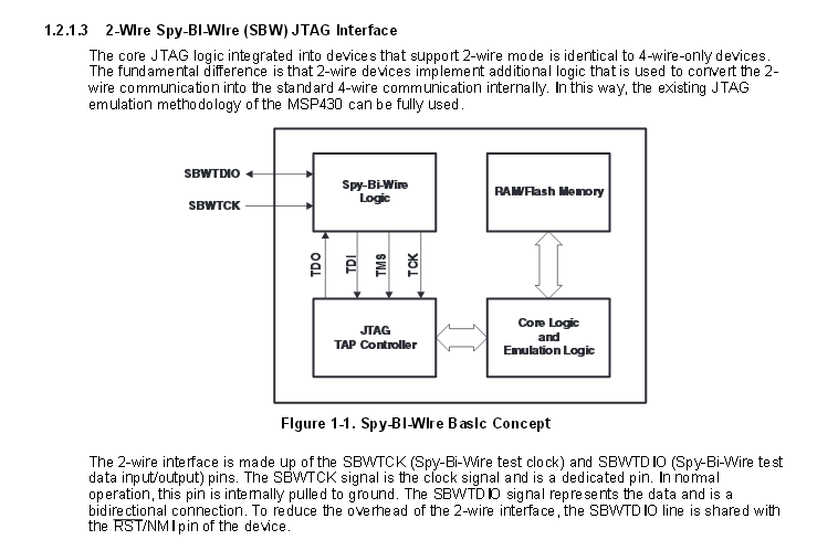
    Most likely using Spy Bi Wire.

    http://www.ti.com/lit/ug/slau320l/slau320l.pdf

  • Sandro,

    There are basically two ways to Erase/Write to MSP430Fxx devices. One way is use the CPU under the proper control of programming code. The other way is to use external signals manipulating some of the special pins of the chip.

    To use the CPU to download into Flash, you need some code before you can load other code. For MSP430F2274, there is a small ROM that has the needed code. This is called BSL.

    To use external signals to download into Flash, you need some external equipment to connect to the so-called JTAG pins of MSP430F2274. TI calls that equipment FET-tool.

    Using JTAG has the additional advantage that you can control the CPU to do single-stepping, set break-point, display & modify memory/register contents, etc. Thus almost all MSP430 development boards has a JTAG connector so that FET-tool can be used. Also all compiler/linker/debugger software can make use of the FET-tool to download and debug the code it generates.

    BSL, on the other hand, is seldom supported except  for volume production and field-update.

  • old_cow_yellow said:
    FET-tool.

    No, just FET. FET-Tools would be like 'LCD-Display'. The 'T' in 'FET' already stands for 'tool'.

    AFAIK, the name was taken because the FET is a tool that turns a standard MSP into a Flash Emulator (like those expensive CPU replacement flash emulators for debugging other architectures) for in-circuit debugging.

**Attention** This is a public forum