This thread has been locked.

If you have a related question, please click the "Ask a related question" button in the top right corner. The newly created question will be automatically linked to this question.

MSP430G2553 to a PN532 for nfc reading and programming

Other Parts Discussed in Thread: MSP430F5659

Good Evening,

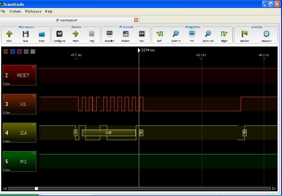
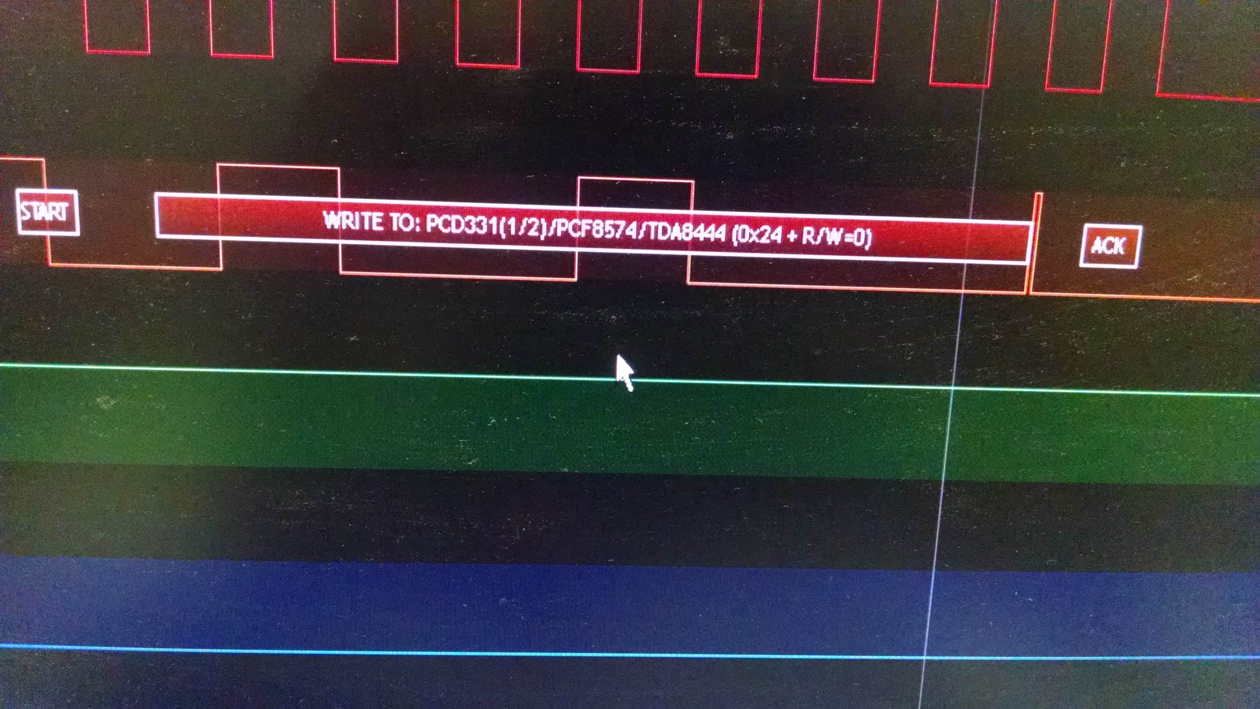
  My task is to program and use a PN532 nfc development board with a msp430 micro controller via I2C.  I have access to a logic level analyzer i use every day and the example code for reading and writing multiple bites hasn't panned out.  I know all the data packs i need to send it and  what it should return but when i send the first data pack it doesn't seem to ack back as well as im having a hard time setting up any example program to read incoming bites right after sending them.  any help on sending a data pack and reading the result accurately perhaps off an example program will be very helpful.  Thank you

  • The forum is full of threads about I2C communication.

    Also, consider a hardware problem. Did you apply the proper pull-up resistors? Look at the signal levels with a scope (not a logic analyzer) and see whether the rising edges are as steep as the falling ones.

    Also, do all peers share a common GND?

  • I have the proper pull up resisters and have been using a scope.  Everything has a common ground.  software wise  i started with some of the example programs for multiple bites sent over i2c.  they may have worked once or twice tops and the one with a library hasn't worked one time

    #include <msp430.h>

    void Port_Mapping(void);

    unsigned char *PTxData; // Pointer to TX data
    unsigned char TXByteCtr;

    const unsigned char TxData[] = // Table of data to transmit
    {
    0x00,
    0x00,
    0xFF,
    0x02,
    0xFE,
    0xD4,
    0x02,
    0x2A
    };

    int main(void)
    {
    unsigned int i;
    // int r = 1;
    WDTCTL = WDTPW | WDTHOLD; // Stop WDT
    Port_Mapping();

    P1SEL = 0;
    // P1SEL2 = 0;
    P1DIR = 0xFF;
    P1OUT = 0x01;
    // P1OUT = 0x00;
    //for(i=0;i<10;i++); // Delay required between transaction
    P2OUT = 0x03;
    P2OUT = 0x00;
    P2OUT = 0x03;
    // P1OUT = 0x01;


    P2SEL |= 0x03; // Assign P2.0 to UCB0SDA and...
    P2DIR |= 0x03; // P2.1 to UCB0SCL

    UCB0CTL1 |= UCSWRST; // Enable SW reset
    UCB0CTL0 = UCMST | UCMODE_3 | UCSYNC; // I2C Master, synchronous mode
    UCB0CTL1 |= UCTR;
    UCB0CTL1 = UCSSEL_2 | UCSWRST; // Use SMCLK, keep SW reset


    UCB0BR0 = 12; // fSCL = SMCLK/12 = ~100kHz
    UCB0BR1 = 0;
    UCB0I2CSA = 0x24; // Slave Address is 048h
    UCB0CTL1 &= ~UCSWRST; // Clear SW reset, resume operation

    for(i=0;i<10;i++); // Delay required between transaction


    PTxData = (unsigned char *)TxData; // TX array start address
    // Place breakpoint here to see each
    // transmit operation.
    TXByteCtr = sizeof TxData; // Load TX byte counter

    UCB0CTL1 |= UCTXSTT; // I2C TX, start condition
    while (UCB0CTL1 & UCTXSTT);

    while(TXByteCtr)
    {
    UCB0TXBUF = *PTxData++; // Load TX buffer
    while (!(UCB0IFG & UCTXIFG));
    TXByteCtr--; // Decrement TX byte counter
    //for(i=0;i<10;i++);
    }
    UCB0CTL1 |= UCTXSTP; // I2C stop condition
    UCB0IFG &= ~UCTXIFG; // Clear USCI_B0 TX int flag

    while (UCB0CTL1 & UCTXSTP); // Ensure stop condition got sent

    //__bic_SR_register_on_exit(LPM0_bits); // Exit LPM0

    __no_operation(); // Remain in LPM0 until all data

    }

    //------------------------------------------------------------------------------
    // The USCIAB0TX_ISR is structured such that it can be used to transmit any
    // number of bytes by pre-loading TXByteCtr with the byte count. Also, TXData
    // points to the next byte to transmit.
    //------------------------------------------------------------------------------
    /*#pragma vector = USCI_B0_VECTOR
    __interrupt void USCI_B0_ISR(void)
    {

    switch(__even_in_range(UCB0IV,12))
    {
    case 0: break; // Vector 0: No interrupts
    case 2: break; // Vector 2: ALIFG
    case 4: break; // Vector 4: NACKIFG
    case 6: break; // Vector 6: STTIFG
    case 8: break; // Vector 8: STPIFG
    case 10: break; // Vector 10: RXIFG
    case 12: // Vector 12: TXIFG
    if (TXByteCtr) // Check TX byte counter
    {
    UCB0TXBUF = *PTxData++; // Load TX buffer
    TXByteCtr--; // Decrement TX byte counter
    }
    else
    {
    UCB0CTL1 |= UCTXSTP; // I2C stop condition
    UCB0IFG &= ~UCTXIFG; // Clear USCI_B0 TX int flag
    __bic_SR_register_on_exit(LPM0_bits); // Exit LPM0
    }
    default: break;
    }
    }
    */

    void Port_Mapping(void)
    {
    // Disable Interrupts before altering Port Mapping registers
    __disable_interrupt();
    // Enable Write-access to modify port mapping registers
    PMAPPWD = 0x02D52;

    #ifdef PORT_MAP_RECFG
    // Allow reconfiguration during runtime
    PMAPCTL = PMAPRECFG;
    #endif

    P2MAP0 = PM_UCB0SDA;
    P2MAP1 = PM_UCB0SCL;

    // Disable Write-Access to modify port mapping registers
    PMAPPWD = 0;
    #ifdef PORT_MAP_EINT
    __enable_interrupt(); // Re-enable all interrupts
    #endif
    }

  • Ok i have changed the pins from port 2 mapped to port 8.  The slave address is 48 which should be correct.  twice since the change in pins i have gotten that result you see on the logic analyzer but most of the time the sda line goes low or stays low.   I have tried looking at individual registers and going through the code as well as change small things such as   while (UCB1CTL1 & UCTXSTT);     which the code sometimes cant make it past so iv commented it out on several tries as well as the    // while ((UCB1IFG & UCTXIFG));    under the buffer.   The UCTR has been set before the SW reset and SMCLK as well as at the same time and iv tried setting the UCTR with the start condition.  I have also tried to make countless small changes to see if it would help to no avail.  changing to pins p8.5 and p8.6 has been slightly more promising as iv got it to send a start condition 48h and a stop condition  (this has only happened a few times so far)  but i did not get an ack back.  the chip im talking to works fine as well with a different micro-controller so it shouldn't be faulty.

    #include <msp430.h>

    //void Port_Mapping(void);

    unsigned char *PTxData; // Pointer to TX data
    unsigned char TXByteCtr;

    const unsigned char TxData[] = // Table of data to transmit
    {
    0x00,
    0x00,
    0xFF,
    0x02,
    0xFE,
    0xD4,
    0x02,
    0x2A
    };

    int main(void)
    {
    unsigned int i;
    // int r = 1;
    WDTCTL = WDTPW | WDTHOLD; // Stop WDT
    //Port_Mapping();

    P1SEL = 0;
    // P1SEL2 = 0;
    P1DIR = 0xFF;
    P1OUT = 0x01;
    // P1OUT = 0x00;
    //for(i=0;i<10;i++); // Delay required between transaction
    // P2OUT = 0x03;
    // P2OUT = 0x00;
    // P2OUT = 0x03;
    // P1OUT = 0x01;


    P8SEL |= 0x60; // Assign P8.5 to UCB1SDA and...
    P8DIR |= 0x60; // P8.6 to UCB1SCL

    UCB1CTL1 |= UCSWRST; // Enable SW reset
    UCB1CTL0 = UCMST | UCMODE_3 | UCSYNC; // I2C Master, synchronous mode
    //UCB0CTL1 |= UCTR;
    UCB1CTL1 = UCTR | UCSSEL_2 | UCSWRST; // Use SMCLK, keep SW reset


    UCB1BR0 = 12; // fSCL = SMCLK/12 = ~100kHz
    UCB1BR1 = 0;
    UCB1I2CSA = 0x48; // Slave Address is 048h
    UCB1CTL1 &= ~UCSWRST; // Clear SW reset, resume operation

    for(i=0;i<10;i++); // Delay required between transaction


    PTxData = (unsigned char *)TxData; // TX array start address
    // Place breakpoint here to see each
    // transmit operation.
    TXByteCtr = sizeof TxData; // Load TX byte counter

    UCB1CTL1 |= UCTXSTT; // I2C TX, start condition
    while (UCB1CTL1 & UCTXSTT);

    while (TXByteCtr)
    {
    UCB1TXBUF = *PTxData++; // Load TX buffer
    // while ((UCB1IFG & UCTXIFG));
    TXByteCtr--; // Decrement TX byte counter
    //for(i=0;i<10;i++);
    }
    UCB1CTL1 |= UCTXSTP; // I2C stop condition
    UCB1IFG &= ~UCTXIFG; // Clear USCI_B1 TX int flag

    while (UCB1CTL1 & UCTXSTP); // Ensure stop condition got sent

    //__bic_SR_register_on_exit(LPM0_bits); // Exit LPM0

    __no_operation(); // Remain in LPM0 until all data

    }

    these o'scope captures where from when it sent the slaves address successfully and did not get a ack back.

    this is the closest thing to working however its only got this far a couple of times. 

  • Robert Breitenstein said:
    The slave address is 48 which should be correct.

    Are you sure? The datasheet doesn't define any slave address for the PN532. So where do you get it from? The one to use is without the R/W bit. So if the 'slave address' you have is 0x48 for write and 0x49 for read, then use 0x24 for the USCI, as this is the real slave address then. (many I2C device manufacturers give you the start byte and not the slave address, for 'convenience')

    Robert Breitenstein said:
    UCB1CTL1 |= UCTXSTT; // I2C TX, start condition
    while (UCB1CTL1 & UCTXSTT);


    In master transmitter mode, the USCI requires you to write something to TXBUF or set UCTXSTP, in order to complete the start byte and clear UCTXSTT.
    After this, you should check for UCNACKIFG, to detect a NACK.

    And of course between writing bytes to TXBUF, you should check for TXIFG being set.

    Robert Breitenstein said:
    UCB1IFG &= ~UCTXIFG; // Clear USCI_B1 TX int flag

    This is superfluous, as setting UCTXSTP will implicitly clear UCTXIFG.

    You might want to not wait for UCTXSTP being cleared again. Do so before starting the next transfer (or reconfiguration), so you can prepare the next transfer while the last byte and the stop are still being sent. This may significantly increase throughput.

  • ok here is the latest with the code i understand what your saying with the slave address that is no longer an issue but this code still tends to send nothing at all over the wires there was a couple of times before i made your corrections that it sent a start 0x48 (slave address with r/w bit) then a stop condition and that was it and it showed up on the O'scope and logic analyzer  i have tried stepping through the code and making sure the registers where set when i expected and how the user guide described them and even the buffer gets filled one part of the array at a time like i want but its not coming through the sda or scl....   which are pulled high by the pull up resistors.   i have tried putting a different controller chip of the same kind in the development board just in case everything on the hardware side of things should be fine and have been rechecked 100 times and by multiple people.

    #include <msp430.h>

    void Port_Mapping(void);

    unsigned char *PTxData; // Pointer to TX data
    unsigned char TXByteCtr;

    const unsigned char TxData[] = // Table of data to transmit
    {
    0x00,
    0x00,
    0xFF,
    0x02,
    0xFE,
    0xD4,
    0x02,
    0x2A
    };

    int main(void)
    {
    unsigned int i;

    WDTCTL = WDTPW | WDTHOLD; // Stop WDT
    Port_Mapping();

    P2SEL |= 0x03; // Assign P2.0 to UCB0SDA and...
    P2DIR |= 0x03; // P2.1 to UCB0SCL

    UCB0CTL1 |= UCSWRST; // Enable SW reset
    UCB0CTL0 = UCMST | UCMODE_3 | UCSYNC; // I2C Master, synchronous mode
    UCB0CTL1 = UCSSEL_2 | UCSWRST; // Use SMCLK, keep SW reset
    UCB0BR0 = 12; // fSCL = SMCLK/12 = ~100kHz
    UCB0BR1 = 0;
    UCB0I2CSA = 0x24; // Slave Address is 048h
    UCB0CTL1 &= ~UCSWRST; // Clear SW reset, resume operation


    for(i=0;i<10;i++); // Delay required between transaction


    PTxData = (unsigned char *)TxData; // TX array start address
    // Place breakpoint here to see each
    // transmit operation.
    TXByteCtr = sizeof TxData; // Load TX byte counter

    UCB0CTL1 |= UCTR | UCTXSTT; // I2C TX, start condition
    while (UCB0CTL1 & UCNACKIFG);

    while (TXByteCtr)
    {
    UCB0TXBUF = *PTxData++; // Load TX buffer
    while ((UCB0IFG & UCTXIFG));
    TXByteCtr--; // Decrement TX byte counter

    }
    UCB0CTL1 |= UCTXSTP; // I2C stop condition
    // UCB0IFG &= ~UCTXIFG; // Clear USCI_B1 TX int flag
    while (UCB0CTL1 & UCTXSTP); // Ensure stop condition got sent

    __no_operation(); // Remain in LPM0 until all data

    }

    void Port_Mapping(void)
    {
    // Disable Interrupts before altering Port Mapping registers
    __disable_interrupt();
    // Enable Write-access to modify port mapping registers
    PMAPPWD = 0x02D52;

    #ifdef PORT_MAP_RECFG
    // Allow reconfiguration during runtime
    PMAPCTL = PMAPRECFG;
    #endif

    P2MAP0 = PM_UCB0SDA;
    P2MAP1 = PM_UCB0SCL;

    // Disable Write-Access to modify port mapping registers
    PMAPPWD = 0;
    #ifdef PORT_MAP_EINT
    __enable_interrupt(); // Re-enable all interrupts
    #endif
    }

  • Robert Breitenstein said:

    TXByteCtr = sizeof TxData; // Load TX byte counter

    UCB0CTL1 |= UCTR | UCTXSTT; // I2C TX, start condition
    while (UCB0CTL1 & UCNACKIFG);

    while (TXByteCtr)
    {
    UCB0TXBUF = *PTxData++; // Load TX buffer
    while ((UCB0IFG & UCTXIFG));
    TXByteCtr--; // Decrement TX byte counter

    }
    UCB0CTL1 |= UCTXSTP; // I2C stop condition

    Try this instead:

    TXByteCtr = sizeof TxData; // Load TX byte counter
    
    UCB0CTL1 |= UCTR | UCTXSTT; // I2C TX, start condition
    
    while (TXByteCtr)
    {
      UCB0TXBUF = *PTxData++; // Load TX buffer
      if(UCB0CTL1 & UCTXSTT) // on first loop, the start byte is still sending)
      {
        while(UCB0CTL1 & UCTXSTT); // wait for start byte done
        if (UCB0CTL1 & UCNACKIFG) // slave didn't answer
          break;
      }
      while (UCB0IFG & UCTXIFG);
      TXByteCtr--; // Decrement TX byte counter
    }
    UCB0CTL1 |= UCTXSTP; // I2C stop condition

    However, except for the wrong NACK handling (and a lockup in case of a NACK), your code should have worked. But I think the port mapping fails.

    IIRC, PMAPPWD is a constant that is already 0x2d52. To unlock the port mapping controller, you'll have to assign it to the PMAPKEYID register:

    PMAPKEYID = PMAPPWD; I'm not 100% sure because I don't know the exact definition of PMAPPWD (the users guide names the content of the PMAPKEYID register PMAPKEYx, PMAPPWD is not mentioned at all)

    Looking at the thread title, I have a question I should have asked before: What MSP are you using? The G2553 does not have a port mapping controller, nor does it have a Port8.

  • i will try your code but you might be right about the port mapping.  the MSP im using is the MSP430F5659.  iv had several variants of code that should of worked and iv been worried that port mapping was the issue but that part of the code iv got from one of the example programs that i do believe should of worked for this MSP.  i briefly switched to port8 to see if it was port mapping issues because port 8 for this msp doesn't have to be mapped.  it sent a start, a 0x48, and a stop condition after a nack but it did not do this reliably.  now the pins we will be using on PCB are p2.0 and p2.1 so i switched back.  

  • Ok i have included your code and changed two parts to the port mapping.  

    void Port_Mapping(void)
    {
    // Disable Interrupts before altering Port Mapping registers
    __disable_interrupt();
    // Enable Write-access to modify port mapping registers
    // PMAPPWD = 0x02D52;
    PMAPKEYID = 0x02D52; // changed from PMAPPWD per user guid
    #ifdef PORT_MAP_RECFG
    // Allow reconfiguration during runtime
    PMAPCTL = PMAPRECFG;
    #endif

    P2MAP0 = PM_UCB0SDA;
    P2MAP1 = PM_UCB0SCL;
    P2SEL |= 0x03; // Assign P2.0 to UCB0SDA and...
    P2DIR |= 0x03;
    // Disable Write-Access to modify port mapping registers
    PMAPKEYID = 0;
    #ifdef PORT_MAP_EINT
    __enable_interrupt(); // Re-enable all interrupts
    #endif
    }

    This definitely makes the SDA and SDL active but it still is not doing what it needs too.

    above is the SDA line it seems to do this constantly now even while the tx buffer is being loaded with what i want as i step through the code and check the registers.

    above is the SCL which it does not stop running the clk constantly.  

      The code i posted is the same except with your suggested change and the port mapping change where i changed PMAPPWD to PMAPKEYID after finding it in the user guide this seemed more correct.  

    any ideas?

  • It looks like there is a clock on SCL, but SDA is open circuit (not even pulled up) and catches crosstalk from SCL. The signal has only 50700mV hysteresis, which is definitely no properly driven output signal.

    At the end of your main, no_operation() doesn't wait for anything. it just wastes one single CPU cycle and then continues. Into the void, as there is no OS, main could return to (depending on the compiler-specific startup code, the MSP might enter LPM4 or reset or enter a while(1) loop or whatever, it is not defined.

    One thing I noticed when looking at the datasheet: while the pin assignment of P2 does not list any default mappings, it does have one. By default, the UCB0 I2C signals are on P2.1 (SDA) and P2.2 (SCL). You need to assign PM_NONE to P2MAP2 or you'll have a secondary output (and worse, input) to SCL on P2.2. Which will confuse the USCI logic (the USCI won't see the clock pulses it generates in the feedback)

  • Ok sure getting somewhere...    

    ill post the current code and some captures right now i have descovered a new issue where the SDA line goes low sometimes after i run it and stays low dispite the pull up resistor and to fix this just long enough to run code iv just shorted it with the scl real fast it would then go high and i could run my code.  I tryed also setting the internal pull up resistors but it did not help.  

    anyway  now when i run the code with your suggestion as well as the fix in the port maping i get logic levels on the oscope and a clock. when i ran the capture it got the slave adress pluse r/w bite then a 0x32 (which shouldnt be in there at all) both got an ack back then a the stop condition oh and i did get the start condition.  

    #include <msp430.h>


    void Port_Mapping(void);

    unsigned char *PTxData; // Pointer to TX data
    unsigned char TXByteCtr;

    const unsigned char TxData[] = // Table of data to transmit
    {
    0x00,
    0x00,
    0xFF,
    0x02,
    0xFE,
    0xD4,
    0x02,
    0x2A
    };

    int main(void)
    {
    unsigned int i;
    // int r = 1;
    WDTCTL = WDTPW | WDTHOLD; // Stop WDT
    Port_Mapping();

    UCB0CTL1 |= UCSWRST; // Enable SW reset
    UCB0CTL0 = UCMST | UCMODE_3 | UCSYNC; // I2C Master, synchronous mode
    UCB0CTL1 = UCSSEL_2 | UCSWRST; // Use SMCLK, keep SW reset
    UCB0BR0 = 12; // fSCL = SMCLK/12 = ~100kHz
    UCB0BR1 = 0;
    UCB0I2CSA = 0x24; // Slave Address is 048h
    UCB0CTL1 &= ~UCSWRST; // Clear SW reset, resume operation

    TXByteCtr = sizeof TxData; // Load TX byte counter

    UCB0CTL1 |= UCTR | UCTXSTT; // I2C TX, start condition

    while (TXByteCtr)
    {
    UCB0TXBUF = *PTxData++; // Load TX buffer
    // while ((UCB0IFG & UCTXIFG));
    if(UCB0CTL1 & UCTXSTT) // on first loop, the start byte is still sending)
    {
    while(UCB0CTL1 & UCTXSTT); // wait for start byte done
    if (UCB0CTL1 & UCNACKIFG) // slave didn't answer
    break;
    }
    while (UCB0IFG & UCTXIFG);
    TXByteCtr--; // Decrement TX byte counter
    }
    UCB0CTL1 |= UCTXSTP; // I2C stop condition


    while (UCB0CTL1 & UCTXSTP); // Ensure stop condition got sent
    __no_operation(); // Remain in LPM0 until all data

    }

    void Port_Mapping(void)
    {
    // Disable Interrupts before altering Port Mapping registers
    __disable_interrupt();
    // Enable Write-access to modify port mapping registers
    // PMAPPWD = 0x02D52;
    PMAPKEYID = 0x02D52; // changed from PMAPPWD per user guid
    #ifdef PORT_MAP_RECFG
    // Allow reconfiguration during runtime
    PMAPCTL = PMAPRECFG;
    #endif

    P2MAP0 = PM_UCB0SDA;
    P2MAP1 = PM_UCB0SCL;
    P2MAP2 = PM_NONE;
    P2SEL |= 0x03; // Assign P2.0 to UCB0SDA and...
    P2DIR |= 0x03;
    P2REN |= 0x03;
    // Disable Write-Access to modify port mapping registers
    PMAPKEYID = 0;
    #ifdef PORT_MAP_EINT
    __enable_interrupt(); // Re-enable all interrupts
    #endif
    }

    that is the code as of right now 

    any ideas? and the tx buffer when i step through the code for the first time is not putting my whole array in but that 0x32

  • Ok gotten a lot further along.  I took an example program and that never worked and made the port mapping changes and a few others and it sent my entire array with acks ...   sometimes with quite the pause between the start address+r/w bit but still.  now the goal is to read back what the firmware version is (ie what im asking it for with this array) so as you will see iv made a transmit function and started on the receive...  however it sends the address with r/w bit as a '0' which it needs to be a '1' to read back...   any help would be continued to be appreciated.

    #include <msp430.h>

    void Port_Mapping(void);
    void Transmit(void);
    void Receive(void);
    unsigned char *PTxData; // Pointer to TX data
    unsigned char TXByteCtr;


    unsigned char *PRxData; // Pointer to RX data
    unsigned char RXByteCtr;
    volatile unsigned char RxBuffer[20]; // Allocate 20 byte of RAM

    const unsigned char TxData[] = // Table of data to transmit
    {
    0x00,
    0x00,
    0xFF,
    0x02,
    0xFE,
    0xD4,
    0x02,
    0x2A
    };

    int main(void)
    {
    // unsigned int i;

    WDTCTL = WDTPW | WDTHOLD; // Stop WDT
    Port_Mapping();

    // P2SEL |= 0x03; // Assign P2.0 to UCB0SDA and...
    // P2DIR |= 0x03; // P2.1 to UCB0SCL

    UCB0CTL1 |= UCSWRST; // Enable SW reset
    UCB0CTL0 = UCMST | UCMODE_3 | UCSYNC; // I2C Master, synchronous mode
    UCB0CTL1 = UCSSEL_2 | UCSWRST; // Use SMCLK, keep SW reset
    UCB0BR0 = 12; // fSCL = SMCLK/12 = ~100kHz
    UCB0BR1 = 0;
    UCB0I2CSA = 0x24; // Slave Address is 048h
    UCB0CTL1 &= ~UCSWRST; // Clear SW reset, resume operation
    UCB0IE |= UCTXIE; // Enable TX interrupt
    UCB0IE |= UCRXIE; // Enable RX interrupt

    while (1)
    {
    Transmit();

    while (UCB0CTL1 & UCTXSTP); // Ensure stop condition got sent

    UCB0IFG |= UCRXIFG; // int USCI_B0 RX int flag
    Receive();

    while (UCB0CTL1 & UCTXSTP); // Ensure stop condition got sent


    break;

    /*
    for(i=0;i<10;i++); // Delay required between transaction
    PTxData = (unsigned char *)TxData; // TX array start address
    // Place breakpoint here to see each
    // transmit operation.
    TXByteCtr = sizeof TxData; // Load TX byte counter

    UCB0CTL1 |= UCTR | UCTXSTT; // I2C TX, start condition

    __bis_SR_register(LPM0_bits | GIE); // Enter LPM0, enable interrupts
    __no_operation(); // Remain in LPM0 until all data
    // is TX'd
    while (UCB0CTL1 & UCTXSTP); // Ensure stop condition got sent
    */
    /*
    if(UCB0CTL1 & UCTRXIFG)
    {

    while (1)
    {
    PRxData = (unsigned char *)RxBuffer; // Start of RX buffer
    RXByteCtr = 5; // Load RX byte counter
    while (UCB0CTL1 & UCTXSTP); // Ensure stop condition got sent
    UCB0CTL1 |= UCTXSTT; // I2C start condition

    __bis_SR_register(LPM0_bits | GIE); // Enter LPM0, enable interrupts
    // Remain in LPM0 until all data
    // is RX'd
    __no_operation(); // Set breakpoint >>here<< and
    } // read out the RxBuffer buffer

    }

    break;
    */
    }
    }

    //------------------------------------------------------------------------------
    // The USCIAB0TX_ISR is structured such that it can be used to transmit any
    // number of bytes by pre-loading TXByteCtr with the byte count. Also, TXData
    // points to the next byte to transmit.
    //------------------------------------------------------------------------------
    #pragma vector = USCI_B0_VECTOR
    __interrupt void USCI_B0_ISR(void)
    {
    switch(__even_in_range(UCB0IV,12))
    {
    case 0: break; // Vector 0: No interrupts
    case 2: break; // Vector 2: ALIFG
    case 4: break; // Vector 4: NACKIFG
    case 6: break; // Vector 6: STTIFG
    case 8: break; // Vector 8: STPIFG
    case 10: // Vector 10: RXIFG
    RXByteCtr--; // Decrement RX byte counter
    if (RXByteCtr)
    {
    *PRxData++ = UCB0RXBUF; // Move RX data to address PRxData
    if (RXByteCtr == 1) // Only one byte left?
    UCB0CTL1 |= UCTXSTP; // Generate I2C stop condition
    }
    else
    {
    *PRxData = UCB0RXBUF; // Move final RX data to PRxData
    __bic_SR_register_on_exit(LPM0_bits); // Exit active CPU
    }
    break;
    case 12: // Vector 12: TXIFG
    if (TXByteCtr) // Check TX byte counter
    {
    UCB0TXBUF = *PTxData++; // Load TX buffer
    TXByteCtr--; // Decrement TX byte counter
    }
    else
    {
    UCB0CTL1 |= UCTXSTP; // I2C stop condition
    UCB0IFG &= ~UCTXIFG; // Clear USCI_B0 TX int flag
    __bic_SR_register_on_exit(LPM0_bits); // Exit LPM0
    }
    default: break;
    }
    }


    void Port_Mapping(void)
    {
    // Disable Interrupts before altering Port Mapping registers
    __disable_interrupt();
    // Enable Write-access to modify port mapping registers
    // PMAPPWD = 0x02D52;
    PMAPKEYID = 0x02D52; // changed from PMAPPWD per user guid
    #ifdef PORT_MAP_RECFG
    // Allow reconfiguration during runtime
    PMAPCTL = PMAPRECFG;
    #endif

    P2MAP0 = PM_UCB0SDA;
    P2MAP1 = PM_UCB0SCL;
    P2MAP2 = PM_NONE;
    P2SEL |= 0x03; // Assign P2.0 to UCB0SDA and...
    P2DIR |= 0x03;
    P2REN |= 0x03;
    // Disable Write-Access to modify port mapping registers
    //PMAPKEYID = 0;
    #ifdef PORT_MAP_EINT
    __enable_interrupt(); // Re-enable all interrupts
    #endif
    }


    void Transmit(void){

    unsigned int i;
    for(i=0;i<10;i++); // Delay required between transaction
    PTxData = (unsigned char *)TxData; // TX array start address
    // Place breakpoint here to see each
    // transmit operation.
    TXByteCtr = sizeof TxData; // Load TX byte counter

    UCB0CTL1 |= UCTR | UCTXSTT; // I2C TX, start condition

    __bis_SR_register(LPM0_bits | GIE); // Enter LPM0, enable interrupts
    __no_operation(); // Remain in LPM0 until all data
    // is TX'd
    while (UCB0CTL1 & UCTXSTP); // Ensure stop condition got sent


    }

    void Receive(void){


    PRxData = (unsigned char *)RxBuffer; // Start of RX buffer
    RXByteCtr = 20; // Load RX byte counter
    while (UCB0CTL1 & UCTXSTP); // Ensure stop condition got sent
    UCB0CTL1 |= UCTR | UCTXSTT; // I2C start condition

    __bis_SR_register(LPM0_bits | GIE); // Enter LPM0, enable interrupts
    // Remain in LPM0 until all data
    // is RX'd
    __no_operation(); // Set breakpoint >>here<< and


    }

  • ok so it seemed to be working and i figured out how to change the r/w bite to 1... however now no matter what i do it doesn't seem to work. what happens now despite all the good earlier results is it goes to my transmit function and trys to send the start condition which i do not think sends correctly then it goes into low power mode and the code stops there with nothing going over the lines that's readable ill post the most current copy of the code as well as a screen shot and i did just try the code from my last post that was working and its doing the same thing even though it worked before any help would be greatly appreciated. 

    #include <msp430.h>

    void Port_Mapping(void);
    //void transmitsetup(void);
    //void Receivesetup(void);
    void Transmit(void);
    void Receive(void);


    unsigned char *PTxData; // Pointer to TX data
    unsigned char TXByteCtr;


    unsigned char *PRxData; // Pointer to RX data
    unsigned char RXByteCtr;
    volatile unsigned char RxBuffer[20]; // Allocate 20 byte of RAM

    const unsigned char TxData[] = // Table of data to transmit
    {
    0x00,
    0x00,
    0xFF,
    0x02,
    0xFE,
    0xD4,
    0x02,
    0x2A
    };

    int main(void)
    {
    //unsigned int i;

    WDTCTL = WDTPW | WDTHOLD; // Stop WDT
    Port_Mapping();

    // P2SEL |= 0x03; // Assign P2.0 to UCB0SDA and...
    //P2DIR |= 0x03; // P2.1 to UCB0SCL
    //P2REN |= 0x03; //pull up resistors
    UCB0CTL1 |= UCSWRST; // Enable SW reset
    UCB0CTL0 = UCMST | UCMODE_3 | UCSYNC; // I2C Master, synchronous mode
    UCB0CTL1 = UCSSEL_2 | UCSWRST; // Use SMCLK, keep SW reset
    UCB0BR0 = 12; // fSCL = SMCLK/12 = ~100kHz
    UCB0BR1 = 0;
    UCB0I2CSA = 0x24; // Slave Address is 024h
    UCB0CTL1 &= ~UCSWRST; // Clear SW reset, resume operation

    UCB0IE |= UCTXIE; // Enable TX interrupt
    //UCB0IE |= UCRXIE; // Enable RX interrupt

    while (1)
    {
    // UCB0CTL1 |= UCTR;
    // UCB0IFG |= UCTXIFG;
    // transmitsetup();
    Transmit();


    while (UCB0CTL1 & UCTXSTP); // Ensure stop condition got sent
    // for(i=0;i<10;i++); // Delay required between transaction

    // Receivesetup();
    // UCB0IFG |= UCRXIFG; // int USCI_B0 RX int flag

    UCB0CTL1 &= ~UCTR;
    Receive();

    while (UCB0CTL1 & UCTXSTP); // Ensure stop condition got sent


    // UCB0CTL1 |= UCTR;

    break;

    }
    }

    //------------------------------------------------------------------------------
    // The USCIAB0TX_ISR is structured such that it can be used to transmit any
    // number of bytes by pre-loading TXByteCtr with the byte count. Also, TXData
    // points to the next byte to transmit.
    //------------------------------------------------------------------------------
    #pragma vector = USCI_B0_VECTOR
    __interrupt void USCI_B0_ISR(void)
    {
    switch(__even_in_range(UCB0IV,12))
    {
    case 0: break; // Vector 0: No interrupts
    case 2: break; // Vector 2: ALIFG
    case 4: break; // Vector 4: NACKIFG
    case 6: break; // Vector 6: STTIFG
    case 8: break; // Vector 8: STPIFG
    case 10: // Vector 10: RXIFG
    RXByteCtr--; // Decrement RX byte counter
    if (RXByteCtr)
    {
    *PRxData++ = UCB0RXBUF; // Move RX data to address PRxData
    if (RXByteCtr == 1) // Only one byte left?
    UCB0CTL1 |= UCTXSTP; // Generate I2C stop condition
    }
    else
    {
    *PRxData = UCB0RXBUF; // Move final RX data to PRxData
    __bic_SR_register_on_exit(LPM0_bits); // Exit active CPU
    }
    break;
    case 12: // Vector 12: TXIFG
    if (TXByteCtr) // Check TX byte counter
    {
    UCB0TXBUF = *PTxData++; // Load TX buffer
    TXByteCtr--; // Decrement TX byte counter

    }
    else
    {
    UCB0CTL1 |= UCTXSTP; // I2C stop condition
    UCB0IFG &= ~UCTXIFG; // Clear USCI_B0 TX int flag
    __bic_SR_register_on_exit(LPM0_bits); // Exit LPM0
    }
    default: break;
    }
    }


    void Port_Mapping(void)
    {
    // Disable Interrupts before altering Port Mapping registers
    __disable_interrupt();
    // Enable Write-access to modify port mapping registers
    // PMAPPWD = 0x02D52;
    PMAPKEYID = 0x02D52; // changed from PMAPPWD per user guid
    #ifdef PORT_MAP_RECFG
    // Allow reconfiguration during runtime
    PMAPCTL = PMAPRECFG;
    #endif

    P2MAP0 = PM_UCB0SDA;
    P2MAP1 = PM_UCB0SCL;
    P2MAP2 = PM_NONE;
    P2SEL |= 0x03; // Assign P2.0 to UCB0SDA and...
    P2DIR |= 0x03;
    P2REN |= 0x03;
    // Disable Write-Access to modify port mapping registers
    // PMAPKEYID = 0;
    #ifdef PORT_MAP_EINT
    __enable_interrupt(); // Re-enable all interrupts
    #endif
    }
    /*
    void transmitsetup(void){


    UCB0CTL1 |= UCSWRST; // Enable SW reset
    UCB0CTL0 = UCMST | UCMODE_3 | UCSYNC; // I2C Master, synchronous mode
    UCB0CTL1 = UCSSEL_2 | UCSWRST; // Use SMCLK, keep SW reset
    UCB0BR0 = 12; // fSCL = SMCLK/12 = ~100kHz
    UCB0BR1 = 0;
    UCB0I2CSA = 0x24; // Slave Address is 048h
    UCB0CTL1 &= ~UCSWRST; // Clear SW reset, resume operation
    UCB0IE |= UCTXIE; // Enable TX interrupt

    }
    */

    void Transmit(void){

    unsigned int i;
    for(i=0;i<10;i++); // Delay required between transaction
    PTxData = (unsigned char *)TxData; // TX array start address
    // Place breakpoint here to see each
    // transmit operation.
    TXByteCtr = sizeof TxData; // Load TX byte counter

    UCB0CTL1 |= UCTXSTT | UCTR; // I2C TX, start condition
    for(i=0;i<10;i++);

    __bis_SR_register(LPM0_bits | GIE); // Enter LPM0, enable interrupts
    __no_operation(); // Remain in LPM0 until all data
    // is TX'd
    while (UCB0CTL1 & UCTXSTP); // Ensure stop condition got sent


    }


    /*
    void Receivesetup(void){


    UCB0CTL1 |= UCSWRST; // Enable SW reset
    UCB0CTL0 = UCMST | UCMODE_3 | UCSYNC; // I2C Master, synchronous mode
    UCB0CTL1 = UCSSEL_2 | UCSWRST; // Use SMCLK, keep SW reset
    UCB0BR0 = 12; // fSCL = SMCLK/12 = ~100kHz
    UCB0BR1 = 0;
    UCB0I2CSA = 0x24; // Slave Address is 048h
    UCB0CTL1 &= ~UCSWRST; // Clear SW reset, resume operation
    UCB0IE &= ~UCTXIE;


    UCB0IE |= UCRXIE; // Enable RX interrupt

    }
    */

    void Receive(void){
    UCB0IE |= UCRXIE;
    // unsigned int i;
    // for(i=0;i<10;i++); // Delay required between transaction
    // UCB0CTL1 &= ~UCTR;
    PRxData = (unsigned char *)RxBuffer; // Start of RX buffer
    RXByteCtr = 20; // Load RX byte counter

    UCB0CTL1 |= UCTXSTT; // I2C start condition

    __bis_SR_register(LPM0_bits | GIE); // Enter LPM0, enable interrupts
    // Remain in LPM0 until all data
    // is RX'd
    __no_operation(); // Set breakpoint >>here<< and


    }

    please not that some parts ie the receive and transmit set ups are voided out these types of things where more of me trying stuff.

    this is what has been the only result for the most part in a while even though i was working as shown in my previous post.

  • One thing you should do is to declare your RX and TX counters as volatile. If you don't, the compiler may delay the update of these variables to the end of the current function or discard it as a redundant write, not knowing that 'magically' an ISR makes use of them outside the current program flow.

    Robert Breitenstein said:
    __bis_SR_register(LPM0_bits | GIE); // Enter LPM0, enable interrupts
    __no_operation(); // Set breakpoint >>here<< and

    No, don't set breakpoint there! Set the breakpoint after this NOP (if necessary, do a second NOP). A breakpoint right after the LPM entry instruction will be triggered before LPM is entered. Because the breakpoint is triggered at instruction fetch, not execution. And the NOP is fetched at the same moment, the previous instruction (LPM  entry) is executed, due to CPU internal pipelining.

    P.s.: Be aware that your RX function won't work if you want to receive just one byte. This special case can only be handled with direct polling of the USCI registers, by setting UCTXSTP right after UCTXSTT clears.

  •   ok i have declared the RX and TX counters as volatile and the break point comment was still there from when i pulled that part off of an example and next time i post my code i will clean up all comments so you know exactly whats going through my head. i tend to set breakpoints in several places when trying to identify a problem to see that its counting right or the buffer is being filled or what not.  and for the rx function i don't believe there will be a need for just one byte with the pn532 im using however i will make a note of that.  

      as of right now (unlike a couple of days ago) the code never makes it to the receive function. (i have looked in the history and compared this code should be just like the one i was using just maybe with more things iv tried being commented out)  At the moment the code goes into the transmit function and i dont think it sends the start command right (see last screen shot of my logic detector) then it does go into the ISR twice decrementing the TXbyte counter by one each time leaving it at 6 however the code then stops in the transmit function when it goes into low power mode.  it goes no further then that and the start condition wasn't sent right.  the transmit function is something ill deal with when the code makes it that far again.  

      any clue as to why it gets stuck where it does or why the start condition isn't sent right?  I have rechecked all the hardware a few times already.

  • Robert Breitenstein said:
    the break point comment was still there from when i pulled that part off of an example and next time i post my code

    I know. Unfortunately, this kind of comment is on all these NOP lines in demo codes. It makes people think that the NOP is there so they can place a breakpoint on it, while it is actually there so they can put a breakpoint on the next instruction without prematurely (and unexpectedly)  triggering a break before LPM is entered (and before any ISR could have been triggered/called).

    Robert Breitenstein said:
    i tend to set breakpoints in several places

    That's a normal approach. However, when dealing with LPMs, the pipelining of the CPU will trigger a breakpoint after the LPM instruction before LPM is entered. So people think their ISRs never got triggered. In fact they didn't have a chance to trigger. If understanding the CPU chapter of the users guide, this is obvious, but for the very most people it is unexpected and makes them looking for a 'bug' that isn't there. And this dreaded comment in the demo code doesn't help.

    Robert Breitenstein said:
    while (TXByteCtr)
    {[...]
    while (UCB0IFG & UCTXIFG);
    TXByteCtr--; // Decrement TX byte counter
    }

    The while is wrong. If UCTXIFG is not set (which it likely isn't on the first loop), this line is skipped, stuffing the next byte into TXBUF while it still contains unsent data. So the unsent data is replaced. However, after a few loops, chances are that TXIFG gets set after writing to TXBUF last time and reaching this while. At this moment, the CPU will be trapped here forever.

    I guess you meant
    while(!(UCB0IFG & UCTXIFG));
    to wait here until TXBUF is free for the next byte.

  •       ok iv made a lot of progress and can post the code if need been but it would be nice to get some advice on a couple of things.  first off from the original code u see is there any way ( now that i have 7 data packs to send and there will be more) to not have as many pointers and such.  also is there a way i can make a .h file and include it into my main.c (i know there is i just dont know what all i can do with it and never made one before dont know where to start) also (maybe as a function) im going to need to pull say 4 bytes of data off of a data pack thats recived and place it into part of a data pack i will then send back out.  first off does the buffer in my code get wrote back over every time? aka can i use a for loop starting from say 8 to fill an array with 4 bytes each time no problem. also how would i go about putting the 4 bytes into a existing data pack thats about to get sent out (And have it alter a packet length bite, packet length checksum, and packet data check sum.  any advice on all that stuff will be greatly appriceated as always 

  •       ok iv made a lot of progress and can post the code if need been but it would be nice to get some advice on a couple of things.  first off from the original code u see is there any way ( now that i have 7 data packs to send and there will be more) to not have as many pointers and such.  also is there a way i can make a .h file and include it into my main.c (i know there is i just dont know what all i can do with it and never made one before dont know where to start) also (maybe as a function) im going to need to pull say 4 bytes of data off of a data pack thats recived and place it into part of a data pack i will then send back out.  first off does the buffer in my code get wrote back over every time? aka can i use a for loop starting from say 8 to fill an array with 4 bytes each time no problem. also how would i go about putting the 4 bytes into a existing data pack thats about to get sent out (And have it alter a packet length bite, packet length checksum, and packet data check sum.  any advice on all that stuff will be greatly appriceated as always

  • I don't really see your problem with the pointers.

    A pointer points to your data. If you don't have a pointer, you don't know where your data is. And you cannot access it anymore. So you need pointers.
    They may be static, global, constant, dynamic or even in a linked chain or an array, but you need them.

    Generally, you can include any text file into a .c file and it is treated as if its content were part of the .c file.
    However, .h files have a special meaning. They contain the declarations (and only those!) of a different .c file, so one .c file can learn what the other one has to offer. A .h file must not generate any code, because it might be included by each and every .c file in a project (leading to linker errors if each time the same code is generated).

    So "int i;" is okay, "int i = 0;" Is not. "void my_func(int parm);" is okay, "void my_func(int parm){...}" is not. A .h file only tells the compiler 'out there, there is something with this name and type', but does not give any implementation details or initializers.

    However, a .h file may also contain constant definitions, macros and enumerations, as these do not generate any code by themselves.

    About your buffer and packet question: What you do with your buffers is what will be done. There are no automatisms. You can read, write and send them back as you want. But you have to do it, it won't happen automatically.

    But these are all more or less generic C language questions and not MSP related.

  •  well what i was talking about with pointers where more about cleaning up the code cause mine is getting quite long now that i have so many arrays to send and so forth.  in many programs iv wrote not on ccsv5 i might for example 

    for(i=0;i<5;i++){

    txbuffer = myarray[i];

    }

    doing this seemed to work fine for many things when i started playing with arrays and now i need a pointer which is ok however id like to shorten everything up like use one pointer and a array thats i change.  what i was thinking was maybe a function where you put in the hex commands you would wanna send or the name of an array with just the data pack then the function adds it into an array ready to send ie  preamble start 00, start command 00 FF, data lenth (lets say 5) 05, lenght check sum FB, then D4, then the data pack i want to send, then a check sum, then post amble of 00.  reason behind me wanting this is first it means less large arrays i have to make and also i will be at one point receiving information into the rxbuffer that about the ninth byte ill need to keep the next 4 bytes and send it back as part of my array so id like to make a function that can have that put in it or whatever data pack i want put in it and maybe create the first part of the array use something like c = sizeof my array (if it can be in hex cause that might be a problem if it couldnt in any way) then transmit[4] = c;...   then id still need to do something with the next byte for the array say transmit[5] = 0x100 - transmit[4]; (if math can be done like that with hex while in code) then i can set transmit[6] = D4; then maybe a for loop for adding what i wanted in my data pack then id still need to set the last byte other then the postamble to be everything from transmit[6] to this byte to equal zero.   what im really trying to do is get a good  idea of how i want to do this.   also sence id have to read some bytes and add them at the end of some arrays to send back to authenticate i figured this kinda way to go about it would be smart.  i still need to know and maybe i can find out for myself later if the rxbuffer array gets started back at zero each time i receive something that way i can pull from that array the data i want cause id know where it is.  also in matlab and several others i know exactly how to have a fuinction with an input but im not sure right off how to make one here.  lets say i want my receive function to accept a number as in receive(8); so that it will receive 8 bytes by setting the rxbytecounter = 8 once at the begining of the function.

    on my transmit function maybe i could say use a name i define for my array thats made for the function i want to send.  these are the kinds of things i need to do next with this project and why im asking these questions.

    i asked about the .h file beacuse i havent had to make one for this or any other project or other .c files for the same project so if they would help me clean up my code some id take any suggestions on how to go about this.   

**Attention** This is a public forum