Other Parts Discussed in Thread: MSP430AFE253
Hi everyone,
I have met a problem when I used SD24_A module in MSP430AFE253 prototype I designed.
Use the internal REF1.2V , and the gain is 1, the maxim input voltage is 0.6V.
It’s registers are set as below:
SD24CTL = SD24REFON+SD24SSEL0; // 1.2V ref, SMCLK
SD24CCTL1 |= SD24SNGL+SD24IE+SD24UNI ; // Single conv, enable interrupt
SD24INCTL1 |= SD24INTDLY0; // Interrupt on 3rd sample
In my test, the sampled data are sent out through UART, and displayed in graph with general tool. I have verified the transferring process.
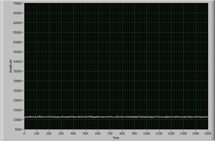
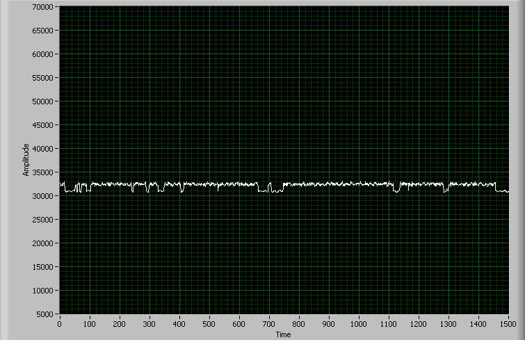
I input three fixed DC voltages, and got their output pictures as below. There is step change in graph when the input voltage nearby 0.3V,
more closing the two input ends(0v and 0.6V), the graph are more smooth.
When I change into Bipolar mode, the result is same.
Can you help me analyze the problem. Thanks.
Input voltage 0.5V

Input voltage 0.3V
Input voltage 0.1V