A related question is a question created from another question. When the related question is created, it will be automatically linked to the original question.
If you have a related question, please click the "Ask a related question" button in the top right corner. The newly created question will be automatically linked to this question.
1.I have got a problem , in a project i used 3 digit 7 segment common cathode display (HX04301BHB), 10 pins, i couldn't indicate pin, which pin is D0,D1,D2 and a b c d e f g please help me!
2. My project is "Heart rate measurement from fingertip"
http://embedded-lab.com/blog/?p=1671
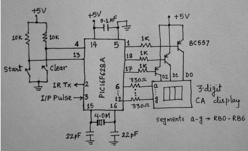
Here used 3 digit common anode 7 segment , 10 pins display. But i have a 3 digit common cathode 7 segment display (HX04301BHB), can i use it by inverting the input of 3 digit 7 segment display by using (74LS04) ic, may it work here?
I heard that there is something called u-tube or you-tube. I do not know what it is, but I know someone who learned to do a lot of things from watching that. There is a catch through, this guy is right-handed and some of the things he learned are demonstrated by left-handed person. Looking him doing those things is very painful.
Where did you get that part?, only info about is in chines. http://www.dzsc.com/data/uploadfile/20113915397805.jpg
8 segments for each led, the 3 digits all shares the high-side connection. You have 3 low side connection, that is the common cathode for each digit.
C is after A, Ground is after Voltage is easy to remember.
So you would now have to multiplex this, the msp430 pin drive is a little weak but if you use 600ohm resistor to 8 mcu pins it probably will be OK and directly drive the 8 hi-side lines.
Now you need 3 more mcu pins that drives 3 npn mosfets for the low-side, Only 1 our of the 3 should ever be on at any time. Now go through each digit about 200 a second and there should be no flicker.
I have 3 digit common cathode 7 segment display (HX04301BHB) , 10 pins
i want to use this replace of 3 digit common anode 7 segment below in this pic.
7 segment display has 10 pins input which pin is D0,D1,D2 and a,b,c,d,e,f,g of the " 3 digit common cathode 7 segment display (HX04301BHB)" , 10 pins ?
7 segment display has 10 pins input which pin is D0,D1,D2 and a,b,c,d,e,f,g of the " 3 digit common cathode 7 segment display (HX04301BHB)" , 10 pins ?
My guess is PIN 8,9 and 12 is each digits Common Cathode (its ground) Use 3v and a 330ohm resistor and poke around and you should be to figure it out, as a LED=Diode and will only lit up if connected correctly.
If it only have 10 pins, but is 3 digits I take it does not have a dot segment. So 7 pins are Anode and 3 pins are Cathode, use a multimeter on diode setting and poke around.
Follow this advice: take a beginners class for electronics.
Sorry, but this problem isn't related to MSP430. It is a (very) basic electronics problem. Anyone with basic electronic skills should be able to do it or at least understand the concept of the solution.
The hints given in this thread should be more than sufficient. if not, then even more detailed help won't help you too. Sorry.