This thread has been locked.

If you have a related question, please click the "Ask a related question" button in the top right corner. The newly created question will be automatically linked to this question.

Interpreting the Ratings for “Schmitt-Trigger Inputs, Ports Px”

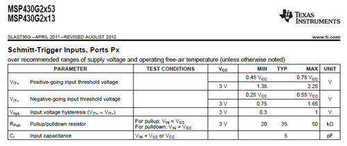
Can somebody spare a moment to explain the ratings shown by the attached table? I'm interested in VIT+ and VIT- . Even after reading SZZA036B, I'm not confident what the ratings actually mean.


For example, do I correctly understand, when interpreting VIT+, that the MIN and MAX values represent a threshold range where a rising voltage must pass through in order for a peripheral to sense the voltage as [digital] high?


And and another thing. It looks like the range is shown for two cases; one for no supply voltage (VCC), and one for 3 V of supply voltage. I don’t understand this. I thought when the supply voltage is zero, the device is off and nothing is working, or is this for some low power mode?

  • Thomas,

    I can help clarify what these parameters in the datasheet mean.  First, V_IT+ is the minimum voltage that must be crossed on a rising edge for the input to be considered high.  Having a minimum of 0.45Vcc and a max of 0.75Vcc just means that the actual threshold value lies somewhere between 0.45Vcc and 0.75Vcc, and can vary from device to device, pin to pin, or even based on the usecase.  The same is true for V_IT-, but in the opposite direction (on a falling edge).

    To explain in a different way, lets take the 3V example that is given in the datasheet.  V_IT+ minimum of 1.35V means that if the input is less that 1.35V, it is guaranteed to NOT be read as a logic high, while a V_IT+ maximum of 2.25V means that an input greater than 2.25V is guaranteed to be read as a logic high.  Again, the same holds true for the V_IT- numbers, but in the opposite direction and as a logic low.

    Where this gets slightly more confusing is when you add in Vhys.  This defines how wide the voltage range is that must be crossed before the input changes to the new logic level.  This is also what allows seemingly invalid overlap between the V_IT+ and V_IT- range of 1.35V to 1.65V in the 3V example.

    To answer your other question regarding the Vcc levels, having a blank Vcc in that table means that it applies to any (allowed) Vcc value.  The 3V line just fills out the calculations for min/max values at 3V.  I.e. for V_IT+ min at 3V, 0.45 * 3V = 1.35V.

    Mike

  • Mike:

    Thank you for answering my question, and thank you for explaining with an example.

    Sincerely,

    Thomas

**Attention** This is a public forum