Because of the holidays, TI E2E™ design support forum responses will be delayed from Dec. 25 through Jan. 2. Thank you for your patience.

This thread has been locked.

If you have a related question, please click the "Ask a related question" button in the top right corner. The newly created question will be automatically linked to this question.

Data Verification Error

Other Parts Discussed in Thread: MSP430FR5739

Hi Everyone,

I'm experiencing problems trying to load code onto my MSP430 FR5739. I'm using the MSP-FET430 UIF with Code Composer 5.4 on Ubuntu 12.04.

I have an extremely simple test program (Code size=154 bytes) that loads every time without incident. As I try to load larger programs on to the controller, I start getting data verification errors. The frequency with which I get data verification errors seems to be dependent on the size of the code I am loading on to the controller. For example, I can successfully program the device ~1/3 times with a code size of 650 bytes and I cannot program the device at all with programs > 900 bytes.

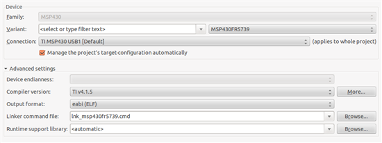
I have checked to make sure that the project device variant is in fact an MSP430FR5739, and that the project is using the appropriate linker file (see image).

I've also checked the address at which the load error occurs and though the address changes every time, it is consistently located in the FRAM code memory as specified in the datasheet. Below are the addresses from the last 5 failed attempts at programming the controller:

0000C606, 0000C5FA, 0000C5E6, 0000C63A, 0000C5E4

The data verification errors stop if I change the verification settings from Full to Fast, but then I get a new error: 

I have checked TI's guide to troubleshooting data verification errors (http://processors.wiki.ti.com/index.php/Troubleshooting_CCS_-_Data_Verification_Errors) and I do not believe the examples described there pertain to my problem. That being said, I'd love to know if I overlooked something.

I would appreciate any solutions, insights or suggestions.

Thanks for the help!

  • I suspect that your problem is caused by the debugger tools you use, or the supporting drivers and dlls.

    Is it possible at all that you can use a different compiler/linker/debugger?

  • A possible reason could be an unstable supply. If voltage drops during programming, it fails. Writing 200 bytes is no problem, for larger amounts, the supply's buffer caps deplete and voltage drops, causing a flash write error.

  • Greg Alexander said:
    The data verification errors stop if I change the verification settings from Full to Fast, but then I get a new error:

    That error suggests a crash / watchdog reset is occurring during the C run time library initialization. One possible cause is WDT fires during C startup code. however, if there really has been a failure programming FRAM then a crash might be occurring due to the FRAM contents being incorrect.

    If CCS reports verification failures, I normally use the free Elprotonic FET-Pro430 http://www.elprotronic.com/fetpro430.html to write / read / verify the program. However, Elprotonic FET-Pro430 looks to be Windows only.

  • Thanks for the help everyone.

    I dug out an FRAM experimenter's board and was able to consistently program the FR5739 with my MSP430-UIF using the same code. I've experienced the watchdog problem in the past, but the code I am currently using disables the watchdog before initialization. I also probed the supply lines during programming and saw stable voltage at Vcc.

    The problem may be that the board was missing the 2.2nF capacitor to the SBWTDIO pin. Thinking this was a RC time constant problem, I increased the size of the 47k pull-up resistor and found that I could load larger code blocks on to the microcontroller. I was able to get as high as 1850 bytes with an open circuit where the 47k pull-up had been. This obviously isn't a good fix.

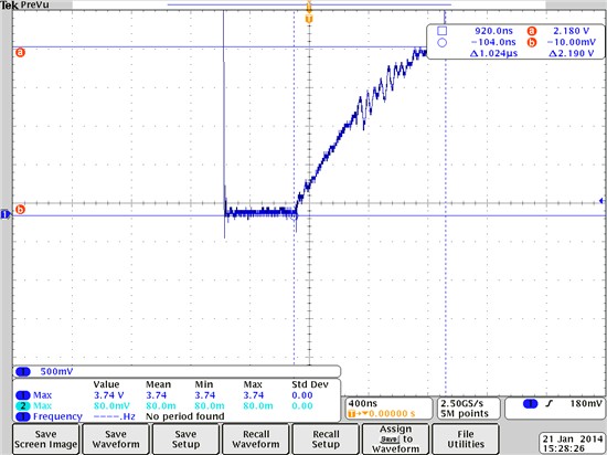
    I probed SBWTCK and the signal seemed okay, but SBWTDIO has some serious issues. Whenever the line is driven low, I see what looks like an RC charging waveform as in the screenshot below, which was taken after the 47k resistor had been removed. Before I removed the resistor, the RC buildup was more pronounced.


    I'm not sure what's causing this waveform. With the 47k resistor removed, there is nothing else on the SBWTDIO line other than the SBWTDIO pin on the microcontroller and the pin on the programmer. Any ideas?

    I've added a 2.2nF capacitor to the design and will order a new board, but doesn't it look like there is a bigger problem here? I removed the 2.2 nF capacitor from the SBWTDIO line of the FRAM experimenter's board and was able to program the controller without any issues. I also able to program a junk board with a MSP430 FR5969 after removing its 2.2nF capacitor. 

    Again, I appreciate all the help!

  • Greg Alexander said:
    Whenever the line is driven low

    ...this causes a reset. As it is the RST pin too. As soon as the pulldown is released, with no external pullup, the voltage begins to rise due to leakage current on the port pin (up to 50pA) and trace parasitic capacitance (a few pF). At a certain point, the internal pullup seems to be activated (high threshold reached, RST considered released, boot code execution begins), causing the RST pin voltage to jump to VCC.

  • The waveform in my previous post was taken during SBW programming. Shouldn't the RST functionality of the pin be disabled during programming?

    With the 47k resistor on the board, the problem is still present (see waveform below). I know the screenshot is not ideal, but notice that now there is a 2.19 V difference between the top and the bottom of the RC charge-up. With an open circuit, the difference is only 1.78 V. If the voltage at the RST pin was reaching a threshold, wouldn't that threshold be the same (or close) for the two different external resistance values (oc and 47k)?

    It seems to me that the programmer is unable to hold the line low for the necessary amount of time, but I'm struggling to come up with reasons as to why this might be. It doesn't look like there is a problem for the first ~500ns.

  • Greg Alexander said:
    Shouldn't the RST functionality of the pin be disabled during programming?

    Yes, section Enable JTAG Access of MSP430™ Programming Via the JTAG Interface User's Guide SLAU320L says:
    Pulling the TEST/SBWTCK pin high enables the SBW interface and disables the RST/NMI functionality of the RST/NMI/SBWTDIO pin. While the SBW interface is active, the internal reset signal is held high, and the internal NMI signal is held at the input value seen at RST/NMI with TEST/SBWTCK going high.
  • Greg Alexander said:
    It seems to me that the programmer is unable to hold the line low for the necessary amount of time, but I'm struggling to come up with reasons as to why this might be. It doesn't look like there is a problem for the first ~500ns.

    In Spy-Bi-Wire the SBWTDIO pin is bidirectional, and is in input to the MSP430 in the TMS and TDI slots and and output from the MSP430 in the TDO slot. If the "RC charge-up" is only occurring when the SBWTDIO is being switched between input and output it might just be a side effect of not being actively driven by either the MSP430 or MSP-FET430UIF and thus the SBWTDIO is being just slowly pulled by the the RC circuit.

    Greg Alexander said:
    I know the screenshot is not ideal, but notice that now there is a 2.19 V difference between the top and the bottom of the RC charge-up. With an open circuit, the difference is only 1.78 V.

    How is the MSP430 powered and connected to the MSP-FET430UIF?

    Does it follow "Figure 2-3. Signal Connections for 2-Wire JTAG Communication Used by MSP430F5xx and MSP430F6xx Devices" in the MSP430 Hardware User's Guide SLAU278J?

**Attention** This is a public forum