This thread has been locked.

If you have a related question, please click the "Ask a related question" button in the top right corner. The newly created question will be automatically linked to this question.

*** Sending a couple of characters to EEPROM and receiving thoes back through I2C

Other Parts Discussed in Thread: MSP430F47197, MSP430F4794

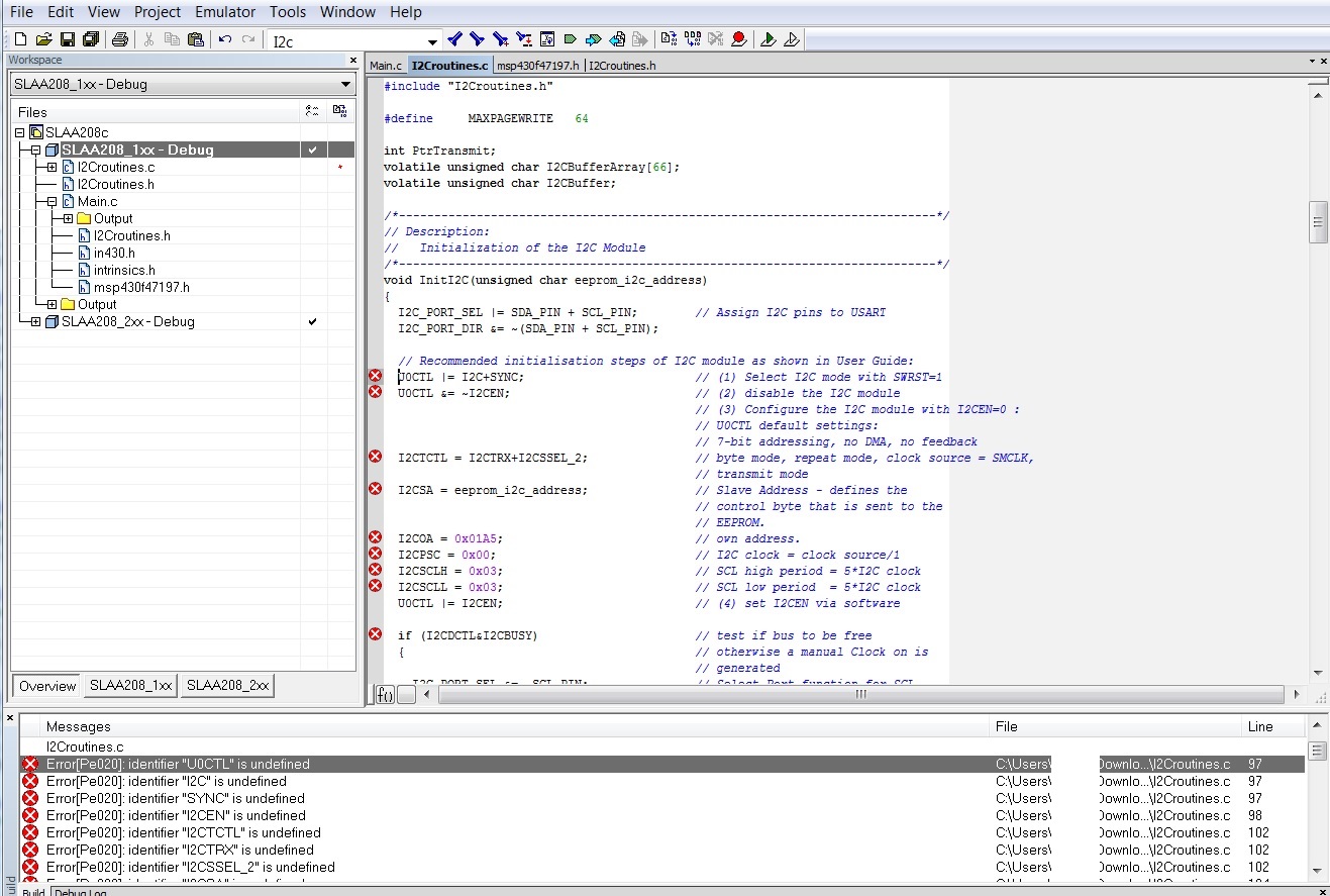
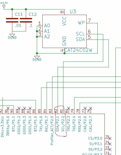
I have MSP430f47197 + an EEPROM (24C02CSN) which are connected to each other through I2C protocol. 

I have my SDA connected to UCB1SDA and SCL is connected to UCB1SCL of MCU.

I think the following code that I partially got it from the example codes sends those characters towards the EEPROM but how I can get those back from EEPROM and show them on the display?

#include "msp430f47197.h"

  
unsigned char *PTxData;                     // Pointer to TX data
volatile unsigned char TXByteCtr;
volatile unsigned char RXByteCtr;

const unsigned char TxData[] =              // Table of data to transmit
{
  0x21,
  0x22,
 0x23,
  0x24,
 0x25
};


int main( void )
{
    volatile unsigned int i;
  // Stop watchdog timer to prevent time out reset
  WDTCTL = WDTPW + WDTHOLD;

  
   FLL_CTL0 |= XCAP11PF;                     // Configure load caps

  // Wait for xtal to stabilize
  do
  {
    IFG1 &= ~OFIFG;                         // Clear OSCFault flag
    for (i = 0x47FF; i > 0; i--);           // Time for flag to set
  }
  while ((IFG1 & OFIFG));                   // OSCFault flag still set?
  
  P5SEL =BIT1+BIT2+BIT3+BIT4;               // Set COM pins for LCD
  LCDACTL = LCDON+LCD4MUX;                  // 4mux LCD, ACLK/32
  LCDAPCTL0 = 0x7F;                         // Segments 0-24
  for( i = 0; i <= 20; i ++)
  {
    LCDMEM[i] = 0;                          // Clear LCD  We have 20 LCDMemory 
  }
  
 
  P2SEL |= BIT1+BIT2;                        // Assign I2C pins to USCI_B1    
  UCB1CTL1 |= UCSWRST;                       // Enable SW reset   
  UCB1CTL1 = UCMODE_3 + UCSYNC;             // I2C Slave, synchronous mode      
 UCB1I2COA =  0x017C;                        // Own Address is 0x017C                 
  UCB1CTL1 &= ~UCSWRST;                     // Clear SW reset, resume operation   
  UCB1I2CIE |= UCSTPIE + UCSTTIE;           // Enable STT and STP interrupt     
  IE2 |= UCB1TXIE;                          // Enable TX interrupt            

  while (1)
  {
    PTxData = (unsigned char *)TxData;      // Start of TX buffer
    TXByteCtr = 0;                          // Clear TX byte count
     UCB1TXBUF = *PTxData++; 
      TXByteCtr++;  
//   RXByteCtr = 0;
//        LCDMEM[2] = UCB1RXBUF; 
//           RXByteCtr++; 
           
          // __delay_cycles(1000000);
  }                                         // read out the TXByteCtr counter
}


  • CaEngineer,

    First, you must read and understand the EEROM data sheet. This is a 5 Volt part, most likely will not work with MSP430.

    Second you cannot just stream bytes to the EEROM. It must be addressed, sent a write command, and register address at which to start writting. Also your MSP430 MUST be the I2C master. There are many examples of how to talk to an EEROM on I2C. Google them.

    Good Luck

  • Hey Corky!

    Yes! It was not as easy as I though! I mean internal flash was easier than setting up an external EEPROM.

    Corky Benson said:
    This is a 5 Volt part, most likely will not work with MSP430.

    I have an external voltage and pretty much sure that I wouldn't have hardware issue.

    Corky Benson said:
    Second you cannot just stream bytes to the EEROM. It must be addressed, sent a write command, and register address at which to start writting.

    Got a good article which is easy to set the address and everything but has too many header files and I got confused. Have you ever used this before?

    http://www.ti.com/lit/an/slaa208a/slaa208a.pdf

    I found I2Croutines.h and .c but they include some-else files and they are all chained! I faced many errors! :(

    Corky Benson said:
    There are many examples of how to talk to an EEROM on I2C. Google them.

    The TI examples honestly are not useful!

  • I do not know which MSP430 you are using. I am using MSP430F4794 and the examples included in the CCS for this part are pretty clear about how to use the USCI for I2C, although not for EEROM specifically. If memory serves, Microchip had some clear appnotes in C, for I2C EEROMS. Keep hunting.

  • Corky Benson said:

    I do not know which MSP430 you are using. I am using MSP430F4794 and the examples included in the CCS for this part are pretty clear about how to use the USCI for I2C, although not for EEROM specifically. If memory serves, Microchip had some clear appnotes in C, for I2C EEROMS. Keep hunting.

    I use MSp430f47197. And I use IAR not CCS. Yes I need to keep-up good jobs!LOL

  • CaEngineer said:
    It was not as easy as I though

    Well, external EEprom is external storage like an HD is, and not an external memory chip like the PC BIOS ROM.

    Most external I2C memory works the same way:

    I2C is a transaction-oriented point-to-point protocol. A transaction goes into one direction only. You start it, send (or receive, depending on direction) and end it.

    To send data to EEProm, you start a transmit operation, send the address, send the data, end the operation.

    To receive form EEprom, you stat a transmit operation, send the address, start a receive operation, receive the data, end the operation. (There is no need to stop the transmit before starting the receive - this is called a "repeated start".)

  • The TI examples are only indicating the I2C between two MSP430f47197. Can I use this method to send data back and forth between an EEPROM and a MSP as well?

  • CaEngineer said:
    The TI examples are only indicating the I2C between two MSP430f47197. Can I use this method to send data back and forth between an EEPROM and a MSP as well?

    Yes. Take i2c master code and modify it to work with EEPROM. Indeed you have to read EEPROM datasheet and follow it while writing EEPROM i/o code.

  • According to the datasheet it works in a range of 1.7 and 5.5 V!
  • I would like to try the following on my MSP. using switches is a good idea to prove that I have a right process of WR/RE.

    https://www.youtube.com/watch?v=XnV-u8ExBFE

  • Having a deeper look at the EEPROM Examples via I2C, found the following one.

    http://www.ti.com/lit/an/slaa208a/slaa208a.pdf

    http://www.ti.com/lit/an/slaa208a/slaa208a.zip  ==> the code

    I use MSP430F47197 which is a member of MSP430F4XX family. However, this example gives me the code for MSP430F2xx. As you can see from the following figure, I just simply changed the header file to 4XX and seems the compiler is not happy with I2C initialization! 

    My question is that how I can get the initialization tailored to 4XX. If I go one by one that would be so time-consuming!

    Is there any way to get around with this?

  • >I use MSP430F47197 which is a member of MSP430F4XX family. However, this example gives me the code for MSP430F2xx.
    >My question is that how I can get the initialization tailored to 4XX. If I go one by one that would be so time-consuming!

    You shall get i2c examples of 4XX chip to familiarize with i2c low level use of 4xx peripherals. Then supposedly you shall be able to "port" EEPROM appnote to 4xx chip.
  • Yes, seems no choice left! The initialization is totally different! however, when it comes to 4XX there are only MASTER-SLAVE examples left! No CPU to EEPROM!

    Let's see how I can get my CAT24C02 EEPROm to work! Seems setting the right interruption acts an important rule to WR/RE into/From EEPROM!

  • The code shown gets you started with the CPU configured as I2C Master. You must now send the proper commands to the E2PROM. Check the memory manufactures' data sheet. The chip has several manufactures, some times one data sheet explains some aspect better than another, so, look at them all. And review all the posts on this thread.

    Good Luck.

  • Hi Corky,

    Yes, I need to initialize the right registers for I2C Protocol!
  • My confusion here is that how to have the MASTER/SLAVE mode get to work with EEPROM/Master! What I did in the following code is to Change the Pin-OUT to transfer the data! (As the figure for EEPROM depicts)

    /* --COPYRIGHT--,BSD_EX
     * Copyright (c) 2012, Texas Instruments Incorporated
     * All rights reserved.
     *
     * Redistribution and use in source and binary forms, with or without
     * modification, are permitted provided that the following conditions
     * are met:
     *
     * *  Redistributions of source code must retain the above copyright
     *    notice, this list of conditions and the following disclaimer.
     *
     * *  Redistributions in binary form must reproduce the above copyright
     *    notice, this list of conditions and the following disclaimer in the
     *    documentation and/or other materials provided with the distribution.
     *
     * *  Neither the name of Texas Instruments Incorporated nor the names of
     *    its contributors may be used to endorse or promote products derived
     *    from this software without specific prior written permission.
     *
     * THIS SOFTWARE IS PROVIDED BY THE COPYRIGHT HOLDERS AND CONTRIBUTORS "AS IS"
     * AND ANY EXPRESS OR IMPLIED WARRANTIES, INCLUDING, BUT NOT LIMITED TO,
     * THE IMPLIED WARRANTIES OF MERCHANTABILITY AND FITNESS FOR A PARTICULAR
     * PURPOSE ARE DISCLAIMED. IN NO EVENT SHALL THE COPYRIGHT OWNER OR
     * CONTRIBUTORS BE LIABLE FOR ANY DIRECT, INDIRECT, INCIDENTAL, SPECIAL,
     * EXEMPLARY, OR CONSEQUENTIAL DAMAGES (INCLUDING, BUT NOT LIMITED TO,
     * PROCUREMENT OF SUBSTITUTE GOODS OR SERVICES; LOSS OF USE, DATA, OR PROFITS;
     * OR BUSINESS INTERRUPTION) HOWEVER CAUSED AND ON ANY THEORY OF LIABILITY,
     * WHETHER IN CONTRACT, STRICT LIABILITY, OR TORT (INCLUDING NEGLIGENCE OR
     * OTHERWISE) ARISING IN ANY WAY OUT OF THE USE OF THIS SOFTWARE,
     * EVEN IF ADVISED OF THE POSSIBILITY OF SUCH DAMAGE.
     *
     *******************************************************************************
     * 
     *                       MSP430 CODE EXAMPLE DISCLAIMER
     *
     * MSP430 code examples are self-contained low-level programs that typically
     * demonstrate a single peripheral function or device feature in a highly
     * concise manner. For this the code may rely on the device's power-on default
     * register values and settings such as the clock configuration and care must
     * be taken when combining code from several examples to avoid potential side
     * effects. Also see www.ti.com/grace for a GUI- and www.ti.com/msp430ware
     * for an API functional library-approach to peripheral configuration.
     *
     * --/COPYRIGHT--*/
    //******************************************************************************
    //   MSP430x471xx Demo - USCI_B0 I2C Master TX multiple bytes to MSP430 Slave
    //
    //   Description: This demo connects two MSP430's via the I2C bus. The master
    //   transmits to the slave. This is the master code. It continuously
    //   transmits an array of data and demonstrates how to implement an I2C
    //   master transmitter sending multiple bytes using the USCI_B0 TX interrupt.
    //   ACLK = 32kHz, MCLK = SMCLK = TACLK = BRCLK = 1MHz
    //
    // ***to be used with "msp430x471x7_uscib0_i2c_09.c" ***
    //
    //                                 /|\  /|\
    //                MSP430x471xx     10k  10k    MSP430x471xx
    //                    slave         |    |        master
    //              -----------------   |    |  -----------------
    //            -|XIN  P3.1/UCB0SDA|<-|---+->|P3.1/UCB0SDA  XIN|-
    //       32kHz |                 |  |      |                 | 32kHz
    //            -|XOUT             |  |      |             XOUT|-
    //             |     P3.2/UCB0SCL|<-+----->|P3.2/UCB0SCL     |
    //             |                 |         |                 |
    //
    //   K. Venkat
    //   Texas Instruments Inc.
    //   May 2009
    //   Built with CCE Version: 3.2.0 and IAR Embedded Workbench Version: 4.11B
    //******************************************************************************
    #include <msp430f47197.h>
    void LCD_init(void);
    void LCD_cmd(unsigned char cmd);     // Definition of LCD Command  
    void LCD_dat(unsigned char byte);         // Definition of LCD Data 
    void DelayMs(int Ms); 
    unsigned char *PTxData;                     // Pointer to TX data
    unsigned char TXByteCtr;
    const unsigned char TxData[] =              // Table of data to transmit
    {
      0x11,
      0x22,
      0x33,
      0x44,
      0x55
    };
    
    int main(void)
    {
      WDTCTL = WDTPW + WDTHOLD;                 // Stop WDT


      //*** LCD Setups
          P7DIR = 0x00; // Redundant
          P8OUT = 0;    // Before set DIR
          P8DIR = 0x07; //P8.2=>EN, P8.1=>RW, P8.0=>RS
          
          DelayMs(100);  // OR USING  __delay_cycles()
          LCD_init();
          DelayMs(50);


      P2SEL |= BIT1+BIT2;                       // Assign I2C pins to the EEPROM    ===> It was P3SEL 
      UCB0CTL1 |= UCSWRST;                      // Enable SW reset
      UCB0CTL0 = UCMST + UCMODE_3 + UCSYNC;     // I2C Master, synchronous mode
      UCB0CTL1 = UCSSEL_2 + UCSWRST;            // Use SMCLK, keep SW reset
      UCB0BR0 = 11;                             // fSCL = SMCLK/11 = 95.3kHz
      UCB0BR1 = 0;
     // UCB0I2CSA = 0x48;                         // Slave Address is 048h
      UCB0CTL1 &= ~UCSWRST;                     // Clear SW reset, resume operation
      IE2 |= UCB0TXIE;                          // Enable TX interrupt
    
      while (1)
      {
        PTxData = (unsigned char *)TxData;      // TX array start address
        TXByteCtr = sizeof TxData;              // Load TX byte counter
        UCB0CTL1 |= UCTR + UCTXSTT;             // I2C TX, start condition
        __bis_SR_register(CPUOFF + GIE);        // Enter LPM0 w/ interrupts
                                                // Remain in LPM0 until all data
                                                // is TX'd
        
        
      LCD_cmd(0x80);
      //LCD_dat();
      
      
        while (UCB0CTL1 & UCTXSTP);             // Loop until STP is TX'd
      }


    }
    
    //------------------------------------------------------------------------------
    // The USCIAB0TX_ISR is structured such that it can be used to transmit any
    // number of bytes by pre-loading TXByteCtr with the byte count. Also, TXData
    // points to the next byte to transmit.
    //------------------------------------------------------------------------------
    #if defined(__TI_COMPILER_VERSION__) || defined(__IAR_SYSTEMS_ICC__)
    #pragma vector = USCIAB0TX_VECTOR
    __interrupt void USCIAB0TX_ISR(void)
    #elif defined(__GNUC__)
    void __attribute__ ((interrupt(USCIAB0TX_VECTOR))) USCIAB0TX_ISR (void)
    #else
    #error Compiler not supported!
    #endif
    {
      if (TXByteCtr)                            // Check TX byte counter
      {
        UCB0TXBUF = *PTxData++;                 // Load TX buffer
        TXByteCtr--;                            // Decrement TX byte counter
      }
      else
      {
        UCB0CTL1 |= UCTXSTP;                    // I2C stop condition
        IFG2 &= ~UCB0TXIFG;                     // Clear USCI_B0 TX int flag
        __bic_SR_register_on_exit(CPUOFF);      // Exit LPM0
      }
    }


    void LCD_cmd(unsigned char cmd)
    {
      P8OUT &= 0xF8; // EN=0,RW=0,RS=0
      P7OUT = cmd;
      
      P8OUT |= 0x04; // En = 1;
      P7DIR = 0xFF;  // out P7
      
      __delay_cycles(2); //Insurance
      
      P8OUT &= 0xFB; // En = 0;
      P7DIR = 0;     // float P7
      
      
      DelayMs(3);
    }
    
    
    void LCD_dat(unsigned char byte)
    {
      P8OUT &= 0xF8; // EN=0,RW=0,RS=0
      P8OUT |= 0x01; // change to RS=1
      P7DIR = 0xFF;  // P7 out
      
      P7OUT = byte;
      
      P8OUT |= 0x04; // EN=1
      
      
      __delay_cycles(2); // Insurance
      
      P8OUT &= 0xFB;  // EN=0
      P7DIR = 0;     //  P7 float
      
      
      DelayMs(3);
    }
    
    void LCD_init(void)
    {
      LCD_cmd(0x38);    // 8-bit mode 5*8 dots ==> Page 17 of the LCD datasheet: Function Set 
      LCD_cmd(0x0C);    // Blinking display   ==> Page 16 of the LCD datasheet: Display ON/OFF Control
      LCD_cmd(0x06);    // Blinking cursor   ==> Page 15 of NMTC-S0802XRGHS: Entry Mode Set 
      LCD_cmd(0x01);    // Clear Display ==> Page 15 of the LCD 
    }
    

    Also, I have added the display functions to show what I have in EEPROM. In other words I would like to ask CPU to give me the EEPROM MEMORIES.

    To do this, what should I do? SDAT is only line to transfer DATA. How can I address the EEPROM then?

  • I just found out that I have the EEPROM code in my firmware of MSP430f47197 that I was not aware of!

    //--------------------------------------------------------------------------
    //
    //  Software for MSP430 based e-meters.
    //
    //  THIS PROGRAM IS PROVIDED "AS IS". TI MAKES NO WARRANTIES OR
    //  REPRESENTATIONS, EITHER EXPRESS, IMPLIED OR STATUTORY, 
    //  INCLUDING ANY IMPLIED WARRANTIES OF MERCHANTABILITY, FITNESS 
    //  FOR A PARTICULAR PURPOSE, LACK OF VIRUSES, ACCURACY OR 
    //  COMPLETENESS OF RESPONSES, RESULTS AND LACK OF NEGLIGENCE. 
    //  TI DISCLAIMS ANY WARRANTY OF TITLE, QUIET ENJOYMENT, QUIET 
    //  POSSESSION, AND NON-INFRINGEMENT OF ANY THIRD PARTY 
    //  INTELLECTUAL PROPERTY RIGHTS WITH REGARD TO THE PROGRAM OR 
    //  YOUR USE OF THE PROGRAM.
    //
    //  IN NO EVENT SHALL TI BE LIABLE FOR ANY SPECIAL, INCIDENTAL, 
    //  CONSEQUENTIAL OR INDIRECT DAMAGES, HOWEVER CAUSED, ON ANY 
    //  THEORY OF LIABILITY AND WHETHER OR NOT TI HAS BEEN ADVISED 
    //  OF THE POSSIBILITY OF SUCH DAMAGES, ARISING IN ANY WAY OUT 
    //  OF THIS AGREEMENT, THE PROGRAM, OR YOUR USE OF THE PROGRAM. 
    //  EXCLUDED DAMAGES INCLUDE, BUT ARE NOT LIMITED TO, COST OF 
    //  REMOVAL OR REINSTALLATION, COMPUTER TIME, LABOR COSTS, LOSS 
    //  OF GOODWILL, LOSS OF PROFITS, LOSS OF SAVINGS, OR LOSS OF 
    //  USE OR INTERRUPTION OF BUSINESS. IN NO EVENT WILL TI'S 
    //  AGGREGATE LIABILITY UNDER THIS AGREEMENT OR ARISING OUT OF 
    //  YOUR USE OF THE PROGRAM EXCEED FIVE HUNDRED DOLLARS 
    //  (U.S.$500).
    //
    //  Unless otherwise stated, the Program written and copyrighted 
    //  by Texas Instruments is distributed as "freeware".  You may, 
    //  only under TI's copyright in the Program, use and modify the 
    //  Program without any charge or restriction.  You may 
    //  distribute to third parties, provided that you transfer a 
    //  copy of this license to the third party and the third party 
    //  agrees to these terms by its first use of the Program. You 
    //  must reproduce the copyright notice and any other legend of 
    //  ownership on each copy or partial copy, of the Program.
    //
    //  You acknowledge and agree that the Program contains 
    //  copyrighted material, trade secrets and other TI proprietary 
    //  information and is protected by copyright laws, 
    //  international copyright treaties, and trade secret laws, as 
    //  well as other intellectual property laws.  To protect TI's 
    //  rights in the Program, you agree not to decompile, reverse 
    //  engineer, disassemble or otherwise translate any object code 
    //  versions of the Program to a human-readable form.  You agree 
    //  that in no event will you alter, remove or destroy any 
    //  copyright notice included in the Program.  TI reserves all 
    //  rights not specifically granted under this license. Except 
    //  as specifically provided herein, nothing in this agreement 
    //  shall be construed as conferring by implication, estoppel, 
    //  or otherwise, upon you, any license or other right under any 
    //  TI patents, copyrights or trade secrets.
    //
    //  You may not use the Program in non-TI devices.
    //
    //  File: iiceeprom.c
    //
    //  Steve Underwood <steve-underwood@ti.com>
    //  Texas Instruments Hong Kong Ltd.
    //
    //  $Id: iiceeprom.c,v 1.5 2008/05/21 08:04:33 a0754793 Exp $
    //
    //--------------------------------------------------------------------------
    #include <stdint.h>
    #include "emeter-toolkit-custom.h"
    #include "emeter-toolkit.h"
    
    // These routines support a single I2C EEPROM or FRAM attached to
    // two pins of a port on an MSP430.
    //
    //Please note:
    //
    // These routines have been tested with an Atmel 2401. They
    // are intended to work with a range of I2C interface serial
    // EEPROMs, but should be thoroughly tested against any
    // other EEPROM before serious use.
    //
    // Since the EEPROM will be operating at a low voltage, when
    // connected to the MSP430, this code is designed to operate
    // at the worst case timing for the Atmel chips, at their
    // lowest recommended supply voltage, and with the MSP430
    // running at 8MHz. They could be tuned for faster operation
    // in other environments.
    
    #if defined(SUPPORT_IICEEPROM)
    
    #define MAX_IIC_TRIES 200
    
    #if defined(EEPROM_IS_REALLY_FRAM)
    /* No delay is needed for FRAMs */
    #define delay(x) /**/
    #else
    /* This delay is needed for EEPROMs */
    static void delay(int i)
    {
        for (  ;  i;  i--)
        {
            _NOP();
            _NOP();
            _NOP();
            _NOP();
        }
    }
    #endif
    
    static void iic_start(void)
    {
        /* Send a start to the EEPROM */
        /* A start is the data bit falling while the clock is high */
        IICEEPROM_PORT_DIR &= ~IICEEPROM_SDA_BIT;
        delay(2);   //At least ???
        IICEEPROM_PORT_DIR &= ~IICEEPROM_SCL_BIT;
        delay(5);   //At least 4.7us
        IICEEPROM_PORT_DIR |= IICEEPROM_SDA_BIT;
        delay(5);   //At least 4.7us
        IICEEPROM_PORT_DIR |= IICEEPROM_SCL_BIT;
    }
    
    static void iic_stop(void)
    {
        /* Send a stop to the EEPROM */
        /* A stop is the data bit rising while the clock is high */
        IICEEPROM_PORT_DIR |= IICEEPROM_SDA_BIT;
        delay(2);   //At least ???
        IICEEPROM_PORT_DIR &= ~IICEEPROM_SCL_BIT;
        delay(5);   //At least 4.7us
        IICEEPROM_PORT_DIR &= ~IICEEPROM_SDA_BIT;
        delay(5);   //At least 4.7us
        IICEEPROM_PORT_DIR |= IICEEPROM_SCL_BIT;
    }
    
    static int iic_send(uint8_t data)
    {
        int i;
        
        /* Send 8 bits of data */
        IICEEPROM_PORT_DIR |= IICEEPROM_SCL_BIT;
        for (i = 8;  i > 0;  i--)
        {
            /* The data can now change without delay */
            if (data & 0x80)
                IICEEPROM_PORT_DIR &= ~IICEEPROM_SDA_BIT;
            else
                IICEEPROM_PORT_DIR |= IICEEPROM_SDA_BIT;
            data <<= 1;
            /* Pulse the clock high while the data bit is steady */
            delay(5);   //At least 4.7us
            IICEEPROM_PORT_DIR &= ~IICEEPROM_SCL_BIT;
            delay(5);   //At least 4.7us
            IICEEPROM_PORT_DIR |= IICEEPROM_SCL_BIT;
        }
        /* Check the acknowledgement from the EEPROM */
        /* Pulse the clock high, and see what the device says while the clock is high */
        delay(5);
        IICEEPROM_PORT_DIR &= ~IICEEPROM_SDA_BIT;
        delay(5);
        IICEEPROM_PORT_DIR &= ~IICEEPROM_SCL_BIT;
        delay(5);
        i = IICEEPROM_PORT_IN & IICEEPROM_SDA_BIT;
        IICEEPROM_PORT_DIR |= IICEEPROM_SCL_BIT;
        delay(4);
        return i;
    }
    
    static uint8_t iic_receive(int ok)
    {
        uint8_t data;
        int i;
    
        /* Get 8 bits of data */
        IICEEPROM_PORT_DIR &= ~IICEEPROM_SDA_BIT;     //Input
        data = 0;
        for (i = 8;  i > 0;  i--)
        {
            IICEEPROM_PORT_DIR &= ~IICEEPROM_SCL_BIT;
            delay(5);   //At least 4.7us
            data <<= 1;
            if (IICEEPROM_PORT_IN & IICEEPROM_SDA_BIT)
                data |= 0x01;
            IICEEPROM_PORT_DIR |= IICEEPROM_SCL_BIT;
            delay(5);   //At least 4.7us
        }
        /* Send the acknowledgement to the EEPROM */
        if (ok)
            IICEEPROM_PORT_DIR |= IICEEPROM_SDA_BIT;
        else
            IICEEPROM_PORT_DIR &= ~IICEEPROM_SDA_BIT;
        delay(4);
        IICEEPROM_PORT_DIR &= ~IICEEPROM_SCL_BIT;
        delay(4);
        IICEEPROM_PORT_DIR |= IICEEPROM_SCL_BIT;
        IICEEPROM_PORT_DIR &= ~IICEEPROM_SDA_BIT;
        return data;
    }
    
    static int test_SDA(void)
    {
        int i;
      
        iic_stop();
        IICEEPROM_PORT_DIR &= ~IICEEPROM_SDA_BIT;
        delay(4);
        for (i = 16;  i > 0;  i--)
        {
            delay(5);
            if (!(IICEEPROM_PORT_IN & IICEEPROM_SDA_BIT))
                break;
        }
        return i;
    }
    
    int iicEEPROM_read(uint16_t addr, void *dat, int len)
    {
        int i;
        int j;
        uint8_t *p;
    
        for (i = 0;  i < MAX_IIC_TRIES;  ++i)
        {
            if (i)
            {
                /* Read FALSE, retry */
                if (test_SDA())
                    continue;
            }
            iic_start();
    #if EEPROM_PAGE_SIZE == 32
            if (iic_send(0xA0)  ||  iic_send(addr/0x100)  ||  iic_send(addr))
                continue;
    #else
            if (iic_send(0xA0 | ((uint8_t)(addr/0x100)*2))  ||  iic_send(addr))
                continue;
    #endif
            p = (uint8_t *) dat;
    
            iic_start();
    #if EEPROM_PAGE_SIZE == 32
            if (iic_send(0xA1))
                continue;
    #else
            if (iic_send(0xA1 | ((uint8_t)(addr/0x100)*2)))
                continue;
    #endif
            for (j = len;  j > 0;  j--)
                *p++ = iic_receive(TRUE);
            *p = iic_receive(FALSE);
            iic_stop();
            return TRUE;
        }
        iic_stop();
        return FALSE;
    }
    
    int iicEEPROM_write(uint16_t addr, void *dat, int len)
    {
        int i;
        int j;
        int section_len;
        uint8_t *p;
        uint8_t *q;
    
        /* If the write spreads across pages in the EEPROM, we need to split the write
           into sections. */
        q = (uint8_t *) dat;
        while (len > 0)
        {
            if (addr + len > ((addr + EEPROM_PAGE_SIZE) & ~(EEPROM_PAGE_SIZE - 1)))
                section_len = ((addr + EEPROM_PAGE_SIZE) & ~(EEPROM_PAGE_SIZE - 1)) - addr;
            else
                section_len = len;
            for (i = 0;  i < MAX_IIC_TRIES;  ++i)
            {
                if (i)
                {
                    /* Write FALSE, retry */
                    if (test_SDA())
                        continue;
                }
    
                iic_start();
    #if EEPROM_PAGE_SIZE == 32
                if (iic_send(0xA0)  ||  iic_send(addr/0x100)  ||  iic_send(addr))
                    continue;
    #else
                if (iic_send(0xA0 | ((uint8_t)(addr/0x100)*2))  ||  iic_send(addr))
                    continue;
    #endif
                p = q;
                for (j = section_len;  j > 0;  j--)
                {
                    if (iic_send(*p++))
                        break;
                }
                if (j == 0)
                    break;
                iic_stop();
            }
            iic_stop();
            if (i >= MAX_IIC_TRIES)
                return FALSE;
            len -= section_len;
            addr += section_len;
            q += section_len;
        }
        return TRUE;
    }
    
    int iicEEPROM_init(void)
    {
        int i;
    
        /* While idling, the EEPROM clock should be low */
        IICEEPROM_PORT_DIR |= IICEEPROM_SCL_BIT;
        /* If we happen to have restarted in the middle of a read from
           the EEPROM/FRAM, we need to regain control of the device. If we
           give it enough clocks, and do no acknowledge it we should get out
           of any odd conditions. Then we do a stop, and we should be OK. If
           the device was mid write when the restart occurred we cannot really
           act in a clean way. */
        delay(5);   //At least 4.7us
        for (i = 0;  i < 16;  i++)
        {
            IICEEPROM_PORT_DIR &= ~IICEEPROM_SCL_BIT;
            delay(5);   //At least 4.7us
            IICEEPROM_PORT_DIR |= IICEEPROM_SCL_BIT;
            delay(5);   //At least 4.7us
        }
        iic_stop();
        return 0;
    }
    #endif
    

    Therefore, I believe that if I call the function from the main, I can get access to the EEPROM! Right? However, what it is confusing is that why some functions are defined as 'Static'?!!!!   in the iiceeprom.c?!

  • Well, actually please disregard my question above. I realized that I do not need the 'Static' functions as they are used within "icc" file. So I just need to use the following functions.

    iicEEPROM_init();
    
    iicEEPROM_write(address to save, Data to write, length);
    
    
     iicEEPROM_read(,,)

    However, I am not quite sure that why I need the data argument to read from the address?!!!!!

    The Reading part is not confusing to you guys?!!!!!! Also, I am not too sure about the length!

  • More specifically, I don't understand what wrong with my code below is?!

     //***************  EEPROM:
             
             
             iicEEPROM_init();
             uint8_t *q;
             char dat = 0xFF;
             q = (uint8_t *) dat;
             iicEEPROM_write(0X00, q, 2);
             
             LCD_cmd(0x80);
             LCD_dat(iicEEPROM_read(0x00,q,2)+0x29);


  • In other words, how can I write into a certain address and read from that immediately?

             //***************  EEPROM:
             
             
             iicEEPROM_init();
             uint8_t *dat;
           //  uint8_t *dat1 ;
             uint8_t dat1 = 56;
     iicEEPROM_write(22,  (uint8_t *) &dat1, sizeof(dat1));
             
             LCD_cmd(0X80);
             LCD_dat(iicEEPROM_read(22, (void *) &dat  ,sizeof(dat)));
             
             
             __delay_cycles(8388608*2); 

  • Ok, now I realized that I do not need the following line.

    iicEEPROM_init();

    As this is coded in the Setup Section of the firmware. However, I am still confused with Read part!

    How can I address this? I still get nothing on the display!!!

  • "The initialization is totally different!"
    Not only the initialization. The code is for the USART module, as found on 1x family and some 2x and 4x family devices. Your MSP has two USCI modules, which are totally different regarding I2C and somewhat different regarding UART and SPI.
    (there are a few 4x devices which have both, USART and USCI).
    So not only the initialization, but also all register names and the whole way to operate I2C transfers are different.
    On USART, you set-up the module for a transfer, start the transfer and wait until an interrupt tells you about success or failure. This setup is quite complex and effectively useless if you have I2C operations like 'write register address, then read register data'. This is why I wrote my own bit-banging I2C code for the 1232 and 1611.
    On USCI, you manage the high-level protocol step-by-step in software, which is less convenient for large-size block transfers but way more useful for short transfers. or command/response combinations. The eUSCI combines both, giving simplicity for ping-pong transfers while providing convenience for block transfers. However, the eUSCI handling for block transfers is not compatible to the USART.

    If you carefully study the users guide, you'll find a timeline chart for I2C master operation (read and write). It tells you the prerequisites and time sequence in which things happen or have to be done on the USCI. Following the chart strictly should give you working code for writing a register address, writing a register address followed by data to write to this register, and read from a register whose address was previously written. You don't even need interrupts (if your application cannot continue anyway until done). So for most I2C devices with register/memory addresses (including the CAT24C02W) , coding is straight:
    configure port pins
    - write slave address to UCBxI2CSA (7 bit address without R/W bit). For the CAT24C02W, it is 0x50 (assuming A0-A2 being low). For teh 512/1k/2k versions, the LSBs are used to address the different 256 byte segments of the memory as if they were multiple 256b devices.
    - Set UCTR and UCTXSTT
    - write memory address to TXBUF
    - wait for UCTXSTT to clear
    - check UCNACKIFG. If set, transfer failed, set UCTXSTP and wait until it clears.
    - If UCNACKIFG is clear, proceed with A or B
    A- write data byte to be written to TXBUF
    - wait for TXIFG to be set again
    - loop to A or
    - set UCTXSTP
    - wait for it to clear again
    - done
    B - clear UCTR
    - set UCTXSTT once more
    - optionally, wait for UCTXSTT to clear and check UCNACKIFG again, but should succeed
    - wait for TXIFG to be set
    - read byte from RXBUF
    - wait for TXIFG for further bytes until all read
    - set UCCTXSTP
    - wait for it to clear
    - done.

    Note that each time you write a byte or read a byte, the internal address counter increases.
    You can write data to 0x56 and then proceed with reading form 0x57 etc.
    In theory, you could also read from an address, then later start a new transfer reading from the next address, without writing the address before. However, this won't work easily, because when you set RXIFG set, theUSCI has already started reading the next byte. So you always read one byte more than you want. Preventing this is tricky, and reading exactly one byte is very tricky. On eUSCI, this is much easier, as you can define a byte count.

    Available demo code is (AFAIK) not ideal for this kind of ping-pong access, as it handles the two transfers as individual transfers rather than a sequence of transfers. But as long as you are the only I2C master and the slave does not choke on a stop condition between the address write and data read transfers, it should do and only waste a bit time between the transfers.

    In the layout image you posted, SDA/SCL is on P2.1/P2.2. So there must be something like P2SEL|= 0x06 in the code to switch these pins from GPIO to USCI mode. Unless the SPI is done by GPIO bit banging. The schematics doesn't show the actual CPU it uses, and the pin names aren't standard. Does it belong to an MSP at all?
  • Michael,


    As I previously mentioned, I was not aware of EEPROM code in my firmware. The figure below depicts what I am going to explain.


    I have iccEEPROM.c in my firmware that includes PINOUT initialization plus RE/WR functions. 

    As CAT24C02 has 16 Byte Page Write Buffer, I just modified my "EEPROM_PAGE_SIZE" register. 

    Then in the main I wrote the following. 


     //***************  EEPROM:


             uint8_t dat = 0x01;


           //  uint8_t *dat;

            // dat = 1;

             iicEEPROM_write(0x50,  (uint8_t *) &dat, sizeof(dat));


             LCD_cmd(0X80);

             LCD_dat(iicEEPROM_read(0x51, (uint8_t *) &dat  ,sizeof(dat)));


       //------------------------------------------     

    My major concern:


    If I write into 0x50, how can I read back from 0x51? And why I have ‘dat’ argument in my Read Function?


    Jens-Michael Gross said:
    Does it belong to an MSP at all?

    Yes, as you can see from the following figure, I use MSP430F47197.


    P.S. The firmware is given by the following link.

    www.ti.com/.../slaa409a.zip


    Jens-Michael Gross said:
    there must be something like P2SEL|= 0x06


      P2SEL |= BIT2;                      /* Select P2.2 for PWM output */


  • The line 'test_SDA()' seems to indicate that it is a software (bit-banging) I2C implementation, not using the USCI.

    "Yes, as you can see from the following figure, "
    I see. The unusual pin names in the device have fooled me.

    "If I write into 0x50, how can I read back from 0x51?"
    If you use the algorithm, I posted above, you can write 0x50, data and then simply read. Writing 0x50 has set the address pointer to 0x50 and writing a byte has incremented it to 0x51. The next read will come from 0x51 then.
    But in your case, the read function has an address parameter and does its own address write before reading.

    "And why I have ‘dat’ argument in my Read Function?"
    A function can only return one single value. In bigger systems with a managed heap, this might be a pointer to a buffer, allocated by the read funciton and filled with the read data. On small systems, you usually pass a pointer to a sufficiently large buffer ( unsigned char * dat or unsigned char dat[x]). The function then writes the data directly into the buffer pointed to by dat and returns either success/failure, or the number of bytes read.
    Likely, you don't want to pass the result of the read function to the LCD but rather 'dat', as it points to the read data.
  • Jens-Michael Gross said:
    The line 'test_SDA()' seems to indicate that it is a software (bit-banging) I2C implementation, not using the USCI.

    Yes, it is Serial Data and uses I2C.

    Jens-Michael Gross said:
    A function can only return one single value. In bigger systems with a managed heap, this might be a pointer to a buffer, allocated by the read funciton and filled with the read data. On small systems, you usually pass a pointer to a sufficiently large buffer ( unsigned char * dat or unsigned char dat[x]). The function then writes the data directly into the buffer pointed to by dat and returns either success/failure, or the number of bytes read.
    Likely, you don't want to pass the result of the read function to the LCD but rather 'dat', as it points to the read data.

    Honestly, I have not understood yet how to show the single bits on my display! I have the following functions for the display mode.

    LCD_cmd()

    LCD_dat()

    Let's say, I pick the first top-most character on the display and I need the address of 0x80 then my LCD_cmd should be as follows.

    LCD_cmd(0x80);

    Now for the LCD_dat() I have no clue how I can put the iccEEPROM_read() function in to it!

    As you say when I write into 0x50, I need to know only the address to retrieve what I had written into my EEPROM. You said that I don't need to pass the result of read. Therefore, do I need to modify the Read function of the EEPROM?

  • "Yes, it is Serial Data and uses I2C."
    Sorry, you misunderstood. Yes, it's I2C. But I2C is the signal protocol. You can generate the signals by various ways, e.g. by pushing and pulling GPIO lines manually, or by using a hardware module like the USCI or the USI or the USART. The 47192 has an USCI module, yet the line 'Test_SDA()" seems to indicate that it might be using a direct GPIO approach. Testing SDA makes not much sense when using the USCI.

    The read function takes the start memory address as first parameter, a pointer to a sufficient memory buffer (alternatively the name of a large-enough non-constant array, which is effectively the same) and the number of bytes to read. I don't know what it returns. Maybe zero if unsuccessful, maybe the same pointer when successful, maybe the number of bytes read into the buffer (0=failure). In any case, it seems you need to pass 'dat' to your LCD, where the read funciton read the data into, and not the return value of the read function.

    iicEEPROM_read(0x51, &dat, sizeof(dat));
    LCD_dat(dat);

    Be sure to clear dat before reading, or it might just still contain the data you tried to write before.
  • CaEngineer said:
    My question is that how I can get the initialization tailored to 4XX. If I go one by one that would be so time-consuming!


    I am curious to know, if I can bypass all of these register tuning unless you get a code designed for the same family of micro controllers.

     here are the code examples for MSp430F4717 

    you can cut/copy most of them directly.

  • Jens-Michael Gross said:
    or by using a hardware module like the USCI or the USI or the USART. The 47192 has an USCI module

    It is called UCB1SDA amd UCB1SCL.

    Jens-Michael Gross said:
    Maybe zero if unsuccessful,

    When I do the following codes:

    //***************  EEPROM:
             uint16_t dat = 0xFF;
             
          
             iicEEPROM_write(0xA0,  (uint16_t *) &dat, sizeof(dat));  // int ==> 160 
    
             iicEEPROM_read(0xA0,  (uint16_t *) &dat, sizeof(dat));
               
             LCD_cmd(0x80);
             LCD_dat((dat)+0x30);
    

    It gives me zero!

    Have I done something wrong then?!

  • sri-sri said:

    I am curious to know, if I can bypass all of these register tuning unless you get a code designed for the same family of micro controllers.

     here are the code examples for MSp430F4717 

    you can cut/copy most of them directly.

    We don't have actual code for EEPROM! They are MAster/Slave modes!

  • Isn't it weird that I got the character which is shown on the below figure when I remove 0x30?!

    There is no such character in the Asci chart!

  • Now your dat is a 16 bit value (uint16_t). That means you're writing two bytes, 0xff to 0xa0 and 0x00 to 0xa1. It is superfluous to cast &dat to uint16_t* as it IS an uint16_t *, the reference pointer to an uint16_t. I guess, the read and write functions are interpreting it as uint8_t* anyway, as the I2C protocol is byte-oriented.
    I don't know what LCD_dat does or expects. Doe sit print a single char, doe sit print a value or does it print a string? No idea. In the last case, it would try to print a string located at address dat+0x30 (perhaps, if the read was successful) 0x012f.

    The ASCII code was not defined for characters above 0x7f. So depending on 'codepage' or such, all characters above 0x7f can show anything. You'll need the font table of your display (or of your LCD driver, if it stuffs the display with bitmap information), to see what code this specific symbol might belong to.
  • Jens-Michael Gross said:
    I don't know what LCD_dat does or expects. Doe sit print a single char, doe sit print a value or does it print a string?

    Here is the LCD_Dat function as follows.

    void LCD_dat(unsigned char byte)
    {
      P8OUT &= 0xF8; // EN=0,RW=0,RS=0
      P8OUT |= 0x01; // change to RS=1
      P7DIR = 0xFF;  // P7 out
      
      P7OUT = byte;
      
      P8OUT |= 0x04; // EN=1
      
      
      __delay_cycles(2); // Insurance
      
      P8OUT &= 0xFB;  // EN=0
      P7DIR = 0;     //  P7 float
      
      
      DelayMs(3);
    }

    So, as you can see it calls character by character! I am guessing that I need to divide my data perhaps to retrieve my data!

    Jens-Michael Gross said:
    The ASCII code was not defined for characters above 0x7f

    Yes, that is called "Extended ASCII Table"!


    void LCD_dat(unsigned char byte){  P8OUT &= 0xF8; // EN=0,RW=0,RS=0  P8OUT |= 0x01; // change to RS=1  P7DIR = 0xFF;  // P7 out    P7OUT = byte;    P8OUT |= 0x04; // EN=1      __delay_cycles(2); // Insurance    P8OUT &= 0xFB;  // EN=0  P7DIR = 0;     //  P7 float      DelayMs(3);}

  • __delay_cycles(2) might be a bit short. I tis only adding 2 MCLK cycles. If you ever speed-up the CPU in the course of your project, it might become too short for the LCD. Otherwise, yes, passing dat to the function should show the character that corresponds to the lower 8 bits of the integer dat.

    Regarding the character code, yes, characters 128 to 255 belong to the extended ASCII table, but there are plenty of different versions of this extensions, the so-called codepages. Each one shows completely different characters, and it is not sure whether your LCD even implements one of these at all, or maybe its own collection of symbols. (similar for the character 0..31, which are defined as function codes, not printable symbols).
    Those who have experience with DOS on a PC, and especially those who live in a non-English country, will well remember the codepage confusion.
    So unless you don't have a printed manual showing you the symbols above 0x80, you don't know what's right or wrong. So better test with something below 0x80.
  • This is getting more fun! I wish I had Saleae EEPROM Analyzre to check the details!

**Attention** This is a public forum