This thread has been locked.

If you have a related question, please click the "Ask a related question" button in the top right corner. The newly created question will be automatically linked to this question.

I2C communication problem in MAP430F5438A

Other Parts Discussed in Thread: MSP430F5438A

Hai every one,

I am trying to communicate between two MSP430F5438a using I2C protocol. One controller i make it as a Master and another controller make it as a Slave. 

i am sending data from slave to master. 

But i unable to see the data in master, what ever i send data from slave. 

my code for Master:

#include <msp430f5438a.h>
#include <stdio.h>

unsigned int RXData;
unsigned char RXCompare;

int main(void)
{
WDTCTL = WDTPW + WDTHOLD; // Stop WDT

P3SEL = BIT7; // P3 selcted as I2c input(SDK)

P5SEL = BIT4; // P5 Selected as I2c output(SCK)

P1DIR |= BIT0;


UCB1CTL1 |= UCSWRST; // Enable SW reset
UCB1CTL0 = UCMST + UCMODE_3 + UCSYNC; // I2C Master, synchronous mode
UCB1CTL1 = UCSSEL_2 + UCSWRST; // Use SMCLK
UCB1BR0 = 12; // fSCL = SMCLK/12 = ~100kHz
UCB1BR1 = 0;
UCB1I2CSA = 0x48; // Slave Address is 048h
UCB1CTL1 &= ~UCSWRST; // Clear SW reset, resume operation
UCB1IE |= UCRXIE; // Enable RX interrupt
RXCompare = 0x0; // Used to check incoming data

while (1)
{
while (UCB1CTL1 & UCTXSTP); // Ensure stop condition got sent
UCB1CTL1 |= UCTXSTT; // I2C start condition
while(UCB1CTL1 & UCTXSTT); // Start condition sent?
UCB1CTL1 |= UCTXSTP; // I2C stop condition

__bis_SR_register(LPM0_bits + GIE); // Enter LPM0, enable interrupts
__no_operation(); // For debugger

}

}

// USCI_B0 Data ISR
#pragma vector = USCI_B1_VECTOR
__interrupt void USCI_B1_ISR(void)
{
switch(__even_in_range(UCB1IV,12))
{
case 0: break; // Vector 0: No interrupts
case 2: break; // Vector 2: ALIFG
case 4: break; // Vector 4: NACKIFG
case 6: break; // Vector 6: STTIFG
case 8: break; // Vector 8: STPIFG
case 10: // Vector 10: RXIFG
RXData = UCB1RXBUF; // Get RX data
P1OUT |= BIT0;
printf("\n %d",RXData);
__bic_SR_register_on_exit(LPM0_bits); // Exit active CPU
break;
case 12: break; // Vector 12: TXIFG
default: break;
}
}

My slave code:

#include <msp430f5438a.h>

unsigned int TXData;
unsigned char i=0;

int main(void)
{
WDTCTL = WDTPW + WDTHOLD; // Stop WDT
// Assign I2C pins to USCI_B0
P5SEL |= BIT4; // Master I2C Clock
P3SEL |= BIT7; // Master I2C Data
P1DIR |= BIT0;
UCB1CTL1 |= UCSWRST; // Enable SW reset
UCB1CTL0 = UCMODE_3 + UCSYNC; // I2C Slave, synchronous mode
UCB1I2COA = 0x48; // Own Address is 048h
UCB1CTL1 &= ~UCSWRST; // Clear SW reset, resume operation
UCB1IE |= UCTXIE + UCSTTIE + UCSTPIE; // Enable TX interrupt
// Enable Start condition interrupt
TXData = 0; // Used to hold TX data

__bis_SR_register(LPM0_bits + GIE); // Enter LPM0 w/ interrupts
__no_operation(); // For debugger
}

// USCI_B0 State ISR
#pragma vector = USCI_B1_VECTOR
__interrupt void USCI_B1_ISR(void)
{
switch(__even_in_range(UCB1IV,12))
{
case 0: break; // Vector 0: No interrupts
case 2: break; // Vector 2: ALIFG
case 4: break; // Vector 4: NACKIFG
case 6: // Vector 6: STTIFG
UCB1IFG &= ~UCSTTIFG; // Clear start condition int flag
break;
case 8: // Vector 8: STPIFG
TXData++; // Increment TXData
UCB1IFG &= ~UCSTPIFG; // Clear stop condition int flag
break;
case 10: break; // Vector 10: RXIFG
case 12: // Vector 12: TXIFG
UCB1TXBUF = TXData; // TX data
P1OUT |= BIT0;
break;
default: break;
}
}

please help me out.


  • Hi,

    How do you have your two MSP430F5438A boards connected? You will need to have VCC and GND for the two boards connected, and connect the two SCL lines together and the two SDA lines together. In addition, you need to add external pull-up resistors on the SCL and SDA lines (as discussed elsewhere on this forum). Does your hardware setup match this exactly?

    Do you have one or both devices connected to MSP-FET430UIF tools for debugging while you are doing this test? If you have both connected instead of just one, you will have to be careful with your settings so that both parts don't get loaded with the same code - you would need to have two separate instances of CCS open and specify a different USB connection for each one under Project > Properties > General > Connections (leave one set to USB1 and set the other to USB2).

    Regards,

    Katie

  • You should not use arithmetic addition operator (+) for combining bits. The compiler won't complain as it treats both as numbers, but depending on the operands, '+' and '|' (the binary OR operator) give different results.

    Do you have proper external pull-ups (<10k) on SDA and SCL? Else the transfer will stall.

    You enter LPM after STT clears and stop was issued. However, you didn't check for UCNACKIFG. If the slave didn't ACK (or the master didn't see the ACK for some reason), the RX interrupt will never trigger. It could be a wiring problem.

    RXData must be declared volatile. Else main might not see any change done to it inside the ISR (and v.v.) due to code optimizations.

    What is RXCompare for? It's set to 0 once, but then never touched again.

    Don't set a breakpoint on the instruction right after entering LPM. The breakpoint will be triggered at the moment LPM is entered, and not after LPM is exited. The "for debugger" comment does not mean 'put a breakpoint here' but rather 'put this NOP here so you can safely put a breakpoint on the next instruction after it.' It has to do with the instruction prefetch mechanism.
    So when you did put a breakpoint there, it is normal you haven't received anything (yet).

  • Hai Katie, 

    Thanks for reply,

    Katie Pier said:

    How do you have your two MSP430F5438A boards connected? You will need to have VCC and GND for the two boards connected, and connect the two SCL lines together and the two SDA lines together. In addition, you need to add external pull-up resistors on the SCL and SDA lines (as discussed elsewhere on this forum). Does your hardware setup match this exactly?

    Yes i connected MSP430F548A boards with two pull up resistors. configuration is like this. Master and slave boards of SDA  pin is connected one end of 10K resistor(same case for SCL also) and other end of resistance is connected to VCC(3V).

    Katie Pier said:

    Do you have one or both devices connected to MSP-FET430UIF tools for debugging while you are doing this test? If you have both connected instead of just one, you will have to be careful with your settings so that both parts don't get loaded with the same code - you would need to have two separate instances of CCS open and specify a different USB connection for each one under Project > Properties > General > Connections (leave one set to USB1 and set the other to USB2).

    Yes.. Master Board having FET debugger and slave board is connected to USB connector(for power).

    i am using IAR compiler. when i run master code in on mSP430F5438A board, it is waiting for start condition

     while(UCB1CTL1 & UCTXSTT); // Start condition sent?


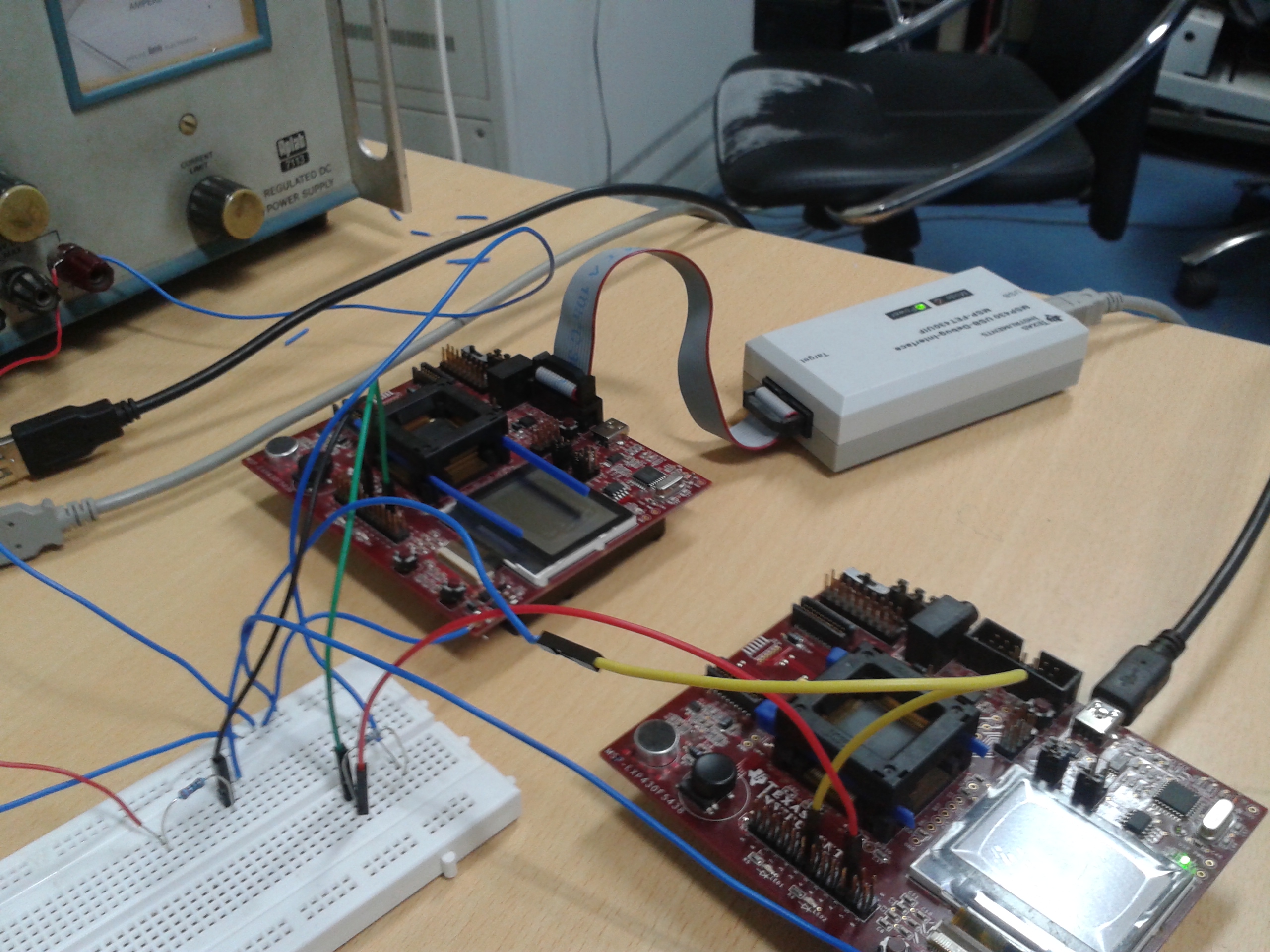
    i am attaching my snap shot of my setup.

  • hai Jens

    Thanks for reply,

    i did changes what u told to me in program, but still i am not getting any data from slave to master.

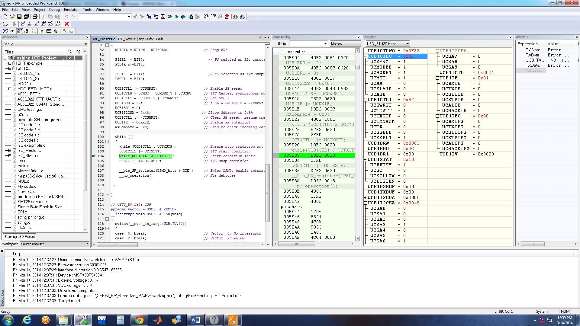
    more over, when i am running my master code, my code is waiting this condition.

     while(UCB1CTL1 & UCTXSTT); // Start condition sent?

    and UCBBUS was set


    i am attaching my snap shot, when program was waiting at that condition. 

  • Hi,

    It seems like you have 3 different Vcc sources going on - I could see this causing issues (looks like you have a bench supply, the FET tool, and the USB power all being used). It might be good to try supplying everything from the same supply. I have seen I2C communication be kind of flake-y before when the two boards are supplied differently, because if everything is not at quite the same level then the thresholds being used for 0 vs 1 on the boards might be slightly off from each other and cause problems.

    You should probably also take an oscilloscope and observe what is happening on your SDA/SCL lines. Seeing your setup you have very long cables and a breadboard all involved, which is not going to help with your I2C communication because in I2C the two boards are both having to control the same lines, just pulling down against the pullup to cause the communication, and then the pullup is the only thing to pull the line high - if you look at it with a scope sometimes your waveform may look really curved (too slow of rise/fall time) like an RC signal, instead of having nice edges, and this may be why you have troubles. If that is the case you can try using a different pullup resistor value, or shorter wires, etc to try to improve the waveform. Sometimes you can also try using a slower communication frequency setting, so that the rise/fall time is a smaller percentage of your bit width.

    Regards,

    Katie

**Attention** This is a public forum