


Hello guys, I am new to this MSP430 world and need some help on the interrupt. I was able to program MSP430G2553 and use P1.3 as the interrupt, and the next step is to enable and disable this interrupt depending on the input logic level of P1.7. Here is a part of the code I wrote down:
while(1) {
if((P1IN & BIT7) == 0x80){ //P1.7 high?
P1IE |= BIT3; // enable P1.3 interrupt
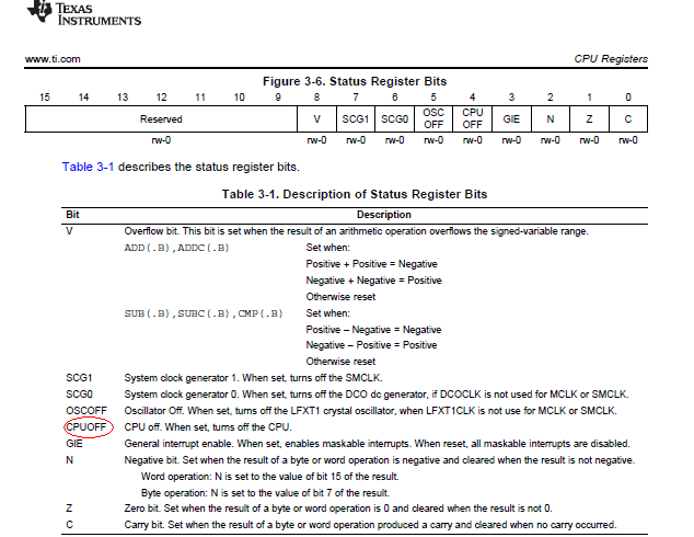
_BIS_SR(CPUOFF + GIE);
} else {
P1IE &= ~BIT3; //disable P1.3 interrupt
}
}
I figured out that once P1.7 goes high, it cannot break from _BIS_SR so P1.7 stays high and never goes back low. I also tried putting '_BIS_SR(CPUOFF + GIE);' before the while loop, but the program never gets to the while loop because of _BIS_SR. It seems I need to do something with _BIS_SR somehow but I don't know how as I just copied the codes from the the tutorials on the internet (frankly, I don't really know what that line means at all...). Please help me out on enabling/disabling the interrupt!!
By the way, does anyone know why P1.1 and P1.2 stays high even if I wrote down P1OUT=0x00?


