


I am having a problem using the watchdog timer ISR on the G2553 launchpad. I want to use switch2 to toggle the LEDs if it is pressed/released. I am using the watchdog timer as a delay for the switch debounce. Port 1 is being used for the button interrupt and the WDT is being used as the delay to reenable the button interrupt.
WHen I try to compile, it says that it the program will not fit in it. I attached a screenshot of the console.
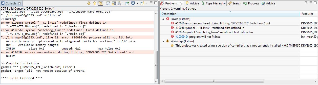
Here is the actual file
/*******************************************************************************
 * main.c
 *
 * 	Created on : April 23, 2012
 * 	      Board: DRV2605EVM-CT REVA
 *
 * Description: This program controls the DRV2605EVK-CT evaluation board.
 *
 * I/O
 * 		   -------------
 * 		  |			P1.0|--> Red LED
 * 		  |			P1.1|--> Green LED
 * 		  |			P1.2|--> Yellow LED
 *	M0 <--|P3.3		P1.3|--> Blue LED
 * 	M1 <--|P3.4			|
 * 	M2 <--|P3.5		P2.0|<-- B1 Button
 * 	M3 <--|P3.6		P2.1|<-- B2 Button
 * 	M4 <--|P3.7  	P2.2|<-- B3 Button
 * 		  |			P2.3|<-- B4 Button
 * 		  |			P2.4|<-- Minus Button
 * SCL <->|P1.6		P2.5|<-- Plus button
 * SDA <->|P1.7		P2.6|--> Load Switch (ERM or LRA)
 * 		  |			P3.1|--> Enable
 * 		  |			P3.2|--> IN/TRIG
 *		   -------------
 *
 * *****************************************************************************/


#include "msp430g2553.h"
//#include "Timer.h"
//#include "I2C.h"
//#include "Haptics.h"
//#include "DRV2605.h"

#define LED0 BIT0
#define LED1 BIT6
#define BUTTON BIT3

unsigned int i;
static unsigned int buttonState = 1;

// Main Function
void main(void)
{
  WDTCTL = WDTPW + WDTHOLD;             // Stop watchdog timer

  // Initialize MSP430 Clocks
  //BCSCTL1 = CALBC1_8MHZ;                // Set DCO to 1, 8, 12 or 16MHz
  //DCOCTL = CALDCO_8MHZ;					// Set MODx to 3
  //BCSCTL1 |= DIVA_0;                    // ACLK/(0:1,1:2,2:4,3:8)
  //BCSCTL2 |= DIVS_0;					// SMCLK/(0=1,1=2,2=4,3=8)
  BCSCTL3 |= LFXT1S_2;                  // LFXT1 = VLO

  P1DIR |= (LED0 + LED1); 	// Set P1.0 to output direction
  P1OUT &= ~(LED0 + LED1);	// set P1.0 to 0 (LED OFF)

  P1DIR &= ~BUTTON;
  P1IFG &= ~BUTTON;			// P1.3 IFG cleared
  P1IE |= BUTTON; 			// P1.3 interrupt enable

  __enable_interrupt(); // enable all interrupts

  while(1)
  {


  }


} 	// End Main

// Port 1 interrupt service routine
#pragma vector=PORT1_VECTOR
__interrupt void Port_1(void)
{
	P1IE &= ~BUTTON;	// disable interrupts for the button to handle bounce
	P1IFG &= ~BUTTON; 	// P1.3 IFG cleared

	/* set watchdog timer to trigger every 16*32.768k/12k = 44 ms */
	WDTCTL = WDT_ADLY_16;
	/* clear watchdog timer interrupt flag */
	IFG1 &= ~WDTIFG;
    /* enable watchdog timer interrupts; in 44 ms the button*/
	IE1 |= WDTIE;

	//P1OUT ^= (LED0 + LED1); // P1.0 = toggle
	if(buttonState < 5)
		buttonState++;
	else
		buttonState = 1;

	switch(buttonState)
	{
		case 1:		//Read Mode
		{
			P1OUT &= ~(LED0 +LED1);
			break;
		}
		case 2:		//Write 1
		{
			P1OUT |= LED1;
			P1OUT &= ~LED0;
			break;
		}
		case 3:		//Write 2
		{
			P1OUT |= LED0;
			P1OUT &= ~LED1;
			break;
		}
		case 4:		//Write 3
		{
			P1OUT |= (LED0 + LED1);
			break;
		}
		default:
		{
			break;
		}
	}

}

#pragma vector=WDT_VECTOR
__interrupt void watchdog_timer(void)
{
    /* Disable interrupts on the watchdog timer */
    IE1 &= ~WDTIE;
    /* clear the interrupt flag for watchdog timer */
    IFG1 &= ~WDTIFG;
    /* resume holding the watchdog timer so it doesn't reset the chip */
    WDTCTL = WDTPW + WDTHOLD;

    /* and re-enable interrupts for the button */
    P1IE |= BUTTON;
}


/******************************************************************************/
// Timer0_A0 Interrupt Service Routine:
/******************************************************************************/
//#pragma vector=TIMER0_A0_VECTOR
//__interrupt void ISR_Timer0_A0(void)
//{
//  TA0CTL &= ~(MC_1);
//  TA0CCTL0 &= ~(CCIE);
//
//  CapTouch_RandomNumber++;
//
//  __bic_SR_register_on_exit(LPM0_bits+GIE);
//}
//
//
//#pragma vector=TIMER1_A1_VECTOR
//__interrupt void Timer_A1_ISR (void)
//{
//  TA1CCTL1 &= ~CCIFG;   //Clear Interrupt Flag
//}
//
Using CCS Version 5.5.0.00077, GCC Compiler IT v4.0.0
