This thread has been locked.

If you have a related question, please click the "Ask a related question" button in the top right corner. The newly created question will be automatically linked to this question.

Error in programing by contacting nedles with 14-conductor cable

Other Parts Discussed in Thread: MSP430F2112

Hi,

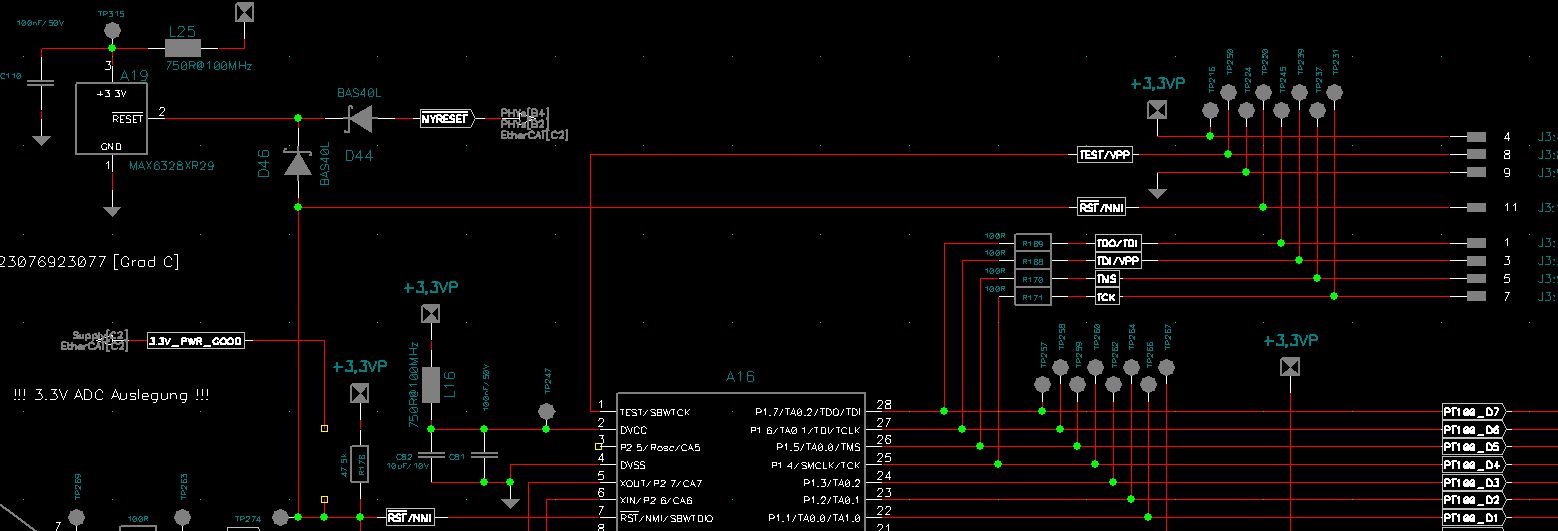
I'm trying to load the firmware on a MSP430F2112 micro using the MSP430 USB-Debug-Interface. Board is inside a test adapter where 12-conductor cable ( I assured that it not exceed 8 inches) acceded test points in the board  through needles to make the connection. I always receive error when I try to execute the mspdebug command:

mspdebug -q uif -j -s

Package is build from the following pieces of software:

MSPGCC: http://sourceforge.net/projects/mspgcc/files/Windows/mingw32/mspgcc-20120406-p20120502.zip
regex: http://sourceforge.net/projects/gnuwin32/files/regex/2.7/regex-2.7-bin.zip/download
libusb-win32: http://sourceforge.net/projects/libusb-win32/files/libusb-win32-releases/1.2.5.0/libusb-win32-bin-1.2.5.0.zip
readline: http://sourceforge.net/projects/gnuwin32/files/readline/5.0-1/readline-5.0-1-bin.zip
mspdebug: git://mspdebug.git.sourceforge.net/gitroot/mspdebug/mspdebug c66e885899f4422b1d57022641a76c17e3301604
MingW: http://www.mingw.org

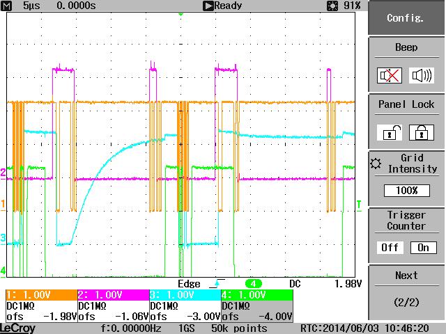
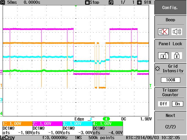
That's error I receive


I supposse it is a HW problem. When I supply the board without test adapter and plug the 14-conductor cable in the connector from board (not in test points) I receive no error.  Mybe signal synchronisation because of  disturbance in test adapter?

i would also like to know wht's the HW meaning of these error messages.

Thanks in advance.

  • Jesus Zafra said:
    I supposse it is a HW problem. When I supply the board without test adapter and plug the 14-conductor cable in the connector from board (not in test points) I receive no error.  Mybe signal synchronisation because of  disturbance in test adapter?

     What means you receive no error? Are you able to debug and program?

     What when doesn't work and what is wrong.

     How is connected your board, are you using JTAG/SBW?

     How reset line is connected? Are capacitor on reset?

     Pease more detail.

  • Sorry,

    I give you more details:

    Roberto Romano said:
    What means you receive no error? Are you able to debug and program?

    Yes. Taht's the case if I try to to debug and program my board out of the test adapter. In this case the test points of my board are not connected by needles and I supplied it from myself. In this conditions I am be able to program it with the command: mspdebug -q uif -j -s

    Roberto Romano said:
     What when doesn't work and what is wrong.

    When I test the board inside test adapter:

    1) First I assure that it is properly supplied by the external power

    2) I also assure that the 14- conductor cable has less than 8 inches

    3) I am not be able to programm it with mpsdebug command

    4) Result of the try is the error message I posted before.

    Roberto Romano said:
    How is connected your board, are you using JTAG/SBW?

    My board is in both cases connected with JTAG connector, 14-conductor cable from USB-Debug Interface to my PC.

    Roberto Romano said:
     How reset line is connected? Are capacitor on reset?

    There is no capacitor on reset. Only a needle is connected with the pin. Could that be the problem? Without the test adapter, reset is not conected with any needle and taht's the case where I can programm the micro.

    What is the meaning of the error message?

    Thank you in advance

  • Jesus Zafra said:
    What is the meaning of the error message?

     I cannot figure what are your problem, please can you take two picture of working and not working arrangement and post both?

  • Jesus Zafra said:

    ... There is no capacitor on reset. Only a needle is connected with the pin. Could that be the problem? ...

    I do not think that is a big problem. Only that it may be sensitive to RF noise.

    Jesus Zafra said:

    ... on reset. Only a needle is connected with the pin ... Without the test adapter, reset is not conected with any needle ...

    Do you mean that the RST pin of the chip is connected to a needle, but that needle is not connected to the JTAG Tool? If so, that is the real problem. There should be a total of 8 connections between the chip and the JTAG Tool. Vcc, Gnd, RST, TEST, and the 4 wire JTAG signals.

  • old_cow_yellow said:
    Do you mean that the RST pin of the chip is connected to a needle, but that needle is not connected to the JTAG Tool? If so, that is the real problem. There should be a total of 8 connections between the chip and the JTAG Tool. Vcc, Gnd, RST, TEST, and the 4 wire JTAG signals.

    No, in the two cases there are always 8 connections.

    I measured some of the JTAG signals with the oscilloscope.

    Channel 1: TCK

    Channel 2: TMS

    Channel 3: TDO/TDI

    CHannel 4: TDI/VPP


    Taht's the case where the firmware is programed without error:

    Taht's the case where the same board is inside a test adapter and I am not be able to program the firmware and error message appears

    You can see here that the Frequence of the clock is lower. Maybe too much noise in adapter affects the clock signal?

    Regards,

    Jesus

  •  Channel 3 appear as if it was disconnected. Is completely different from behave when working.

     Is this pin in metal contact if measured with a tester?

**Attention** This is a public forum