This thread has been locked.

If you have a related question, please click the "Ask a related question" button in the top right corner. The newly created question will be automatically linked to this question.

Bad IRDA reception or: is a MSP430F2272 with IRDA, UCOS16=1 really using majority votes?

Other Parts Discussed in Thread: MSP430F2272

In our application we are suffering from a lot of character loss (bad reception of characters) with IRDA transmissions from a certain device. I have tried to narrow down all the options that cause this but it still isn't fixed.Some background:

For receiving IRDA we use devices with a MSP430F2272 and a Vishay TFDU4101 IRDA transceiver. The bitrate is 57600 bps and with most other devices the setup works fine. The TFDU4101 however has a strange feature that might be the problem here but what I see happening in my test is not what I would understand from the data sheet of the MSP430:

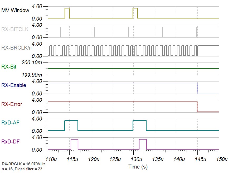
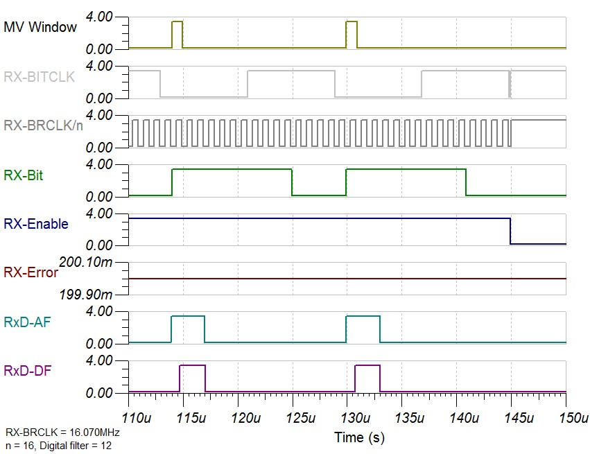
In 57600 communication a bit is 1/57600s long. This is 17.36uS. However in IRDA the bit is shaped to only 3/16 of this (hence the UCOS16=1 setting). That means that the bit is actually a light pulse of 3.255us. HOWEVER the TFDU4101 transceiver will transform each incoming bit (that is longer than 150ns) to a pulse of typically 2.2us.

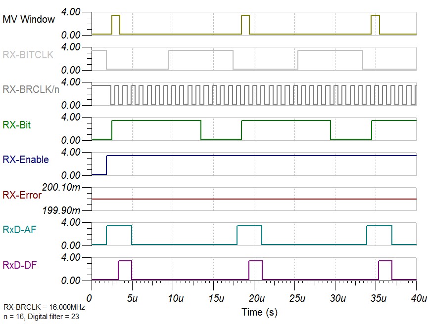
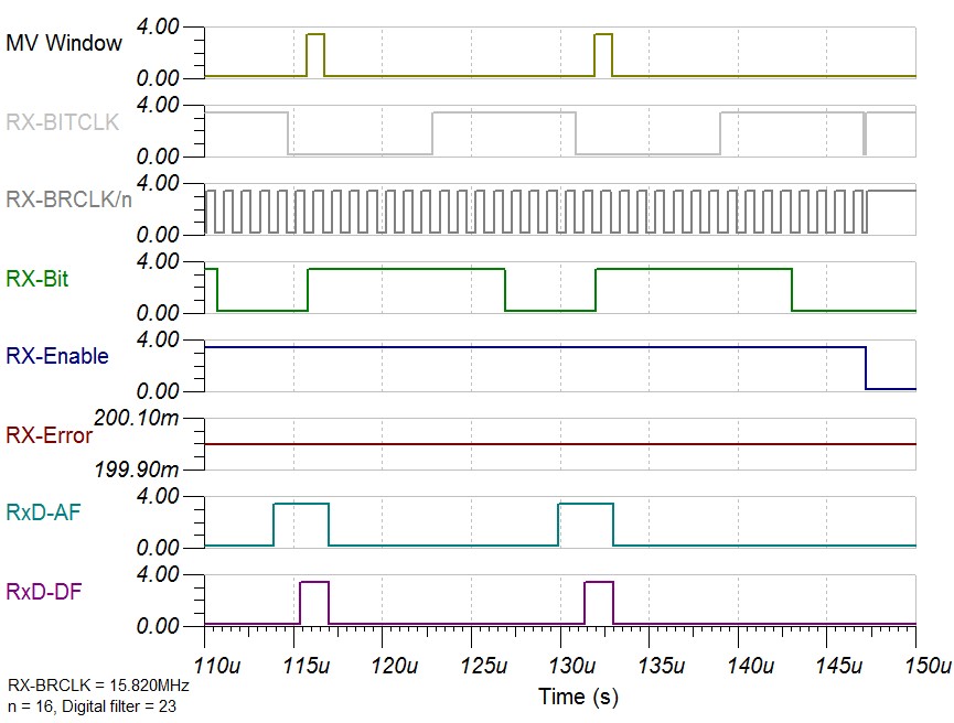
I would therefore guess that the bad communication is caused by the source device having a clock that is slightly off, which is then 'amplified' by the fact that the incoming bit is changed in length from 3.255us to 2.2us. Taking the majority vote (as I undertsand from the literature is taken every 1/16 sample of the bitrate clock with UCOS16=1) would then fail often because the incoming bits are a bit off-sync but also shorter, thus causing the vote often to be '0' instead of '1',

If you take this logic a bit further then the following would happen: start communicating at 9600bps and all reception would fail, because a 9600bps IRDA light pulse is 19.53us long but our transceiver cuts this back to 2.2us! The 16x clock for this bitrate would be 153600 Hz. If a sample is taken using the majority vote, this would be done 3 (?) times every 6.51us, but our signal is no longer 19.53us long but only 2.2us. Thus the majority vote would always fail... This is not what happens! In our test setup (not using the device that causes bad reception on the MSP430 side, but a separate IRDA dongle) communicating at 9600bps over IRDA with this transceiver works just fine.

How can that be? Is the MSP430 maybe not taking a majority vote when IRDA is enabled (UCIREN=1). It seems so. If that is the case what causes the bad reception? Could a source clock being off just a little bit disturb the MSP430 because it samples the incoming bit once and at the 'incorrect time' (from this device's perspective) and this behaviour is worsened by the fact that the bit is also shorter than expected.

Some insights would be appreciated.

  • IrDA uses IR pulses to communicate. For data-rate up to 115.2 kb/s, the pulses are allowed to be as short as 1.41 usec and as long as slightly over 3 / 16 of the bit length. Thus 2.2 usec is fine for all data-rates equal or below 115.2 (and that is probably why Vishay designed their transceivers that way.)

    An IrDA decoder should only rely on the timing of the leading edge of incoming pulses. It should ignore the pulse width and the trailing edge. It should not take majority vote or things like that which applies only to NRZ signals, not pulses.

    I do not know if MSP430F2272 is doing the IrDA decoding correctly or not. Does it work at other data-rates? What other devices did you use to test?

    -- OCY

  • Additionally to OCY, due to the short pulse time the baud rate should be very precise. Tries if it works with minor different baud rate settings. It’s also possible that you need a different baud rate setting for Rx and Tx. Don’t trust the Rx ‘programmable digital filter’ check for proper operation, in some cases it doesn’t work.

  • Thanks for the input. I cannot find explicit information about the timing of IRDA reception in the MSP430. The documentation says (when using UCOS16=1):

    'The oversampling mode is selected when UCOS16 = 1. This mode supports sampling a UART bit stream
    with higher input clock frequencies. This results in majority votes that are always 1/16 of a bit clock period
    apart. This mode also easily supports IrDA pulses with a 3/16 bit-time when the IrDA encoder and decoder
    are enabled.'

    That is indeed true for IRDA transmission, the sent pulses are indeed 3/16 of the selected bitrate so that works fine. Also:

    'When a low period on UCAxRXD exceeds t τ a majority vote is taken for the start bit. If the majority vote
    fails to detect a valid start bit the USCI halts character reception and waits for the next low period on
    UCAxRXD. The majority vote is also used for each bit in a character to prevent bit errors.

    So there is no exception in the literature for IRDA transmissions. Because 9600 baud transmissions work fine in the test setup (which it shouldn't if majority votes are used, because the pulse length is always too short), I don't think the majority votes are used in IRDA as old_cow_yellow suggests.

    --

    I'm a bit further with testing now; I always relied on the factory calibrated 8MHz setting of the MSP430's combined with UCBRx=8, UCBRSx=0 and UCBRFx=11 (as suggested for 57600 in slau144j). The MSP430F2272 only allows for a low frequency crystal, so I now used a 32768Hz crystal to re-calibrate the device at 7.372.800Hz. This  is a nice clock speed for 57600 transmission. In the test setup the msp430 now seems to work better (or even ~100% but not sure about that yet) with the previously malfunctioning device.

    I guess the device that we often couldn't properly communicate with, has a clock that is off together with a msp430 that is also off (in the other direction) using the factory calibrated 8MHz. When using at least one calibrated device, the problem seems to go away.

    So OCY and Leo Bosch; the timing might be the problem after all, but I am still puzzled about majority votes and if they are used or not. At least it seems they are not in IRDA in the MSP430, but it is not in the documentation.

  • The pulse timing (3/16) applies only to the transmitter, the receiver just clocks the current bit (level) in regardless of the pulse length. The majority vote (also with IrDA) applies only to the complete bit-time but when oversampling it’s more precise. Therefore the timing needs more precise, the receiver clock comes easy out of sync.

  • I think I don't understand.

    If the receiver only clocks in a bit regardless of the pulse length, it should do this at the exact moment. If a pulse is 3/16 of the bitrate I'd assume that the 'clocking in' would be done at the 2nd the 3/16 bit-length (trying to do this in the middle of the bit-pulse to allow for some clock drift between the devices). But if the receiver assumes the bit to be 3/16 long while it isn't this goes wrong very easily. Or does the receiver measure the width of the incoming pulse (the start bit) and then use the middle of that for the next measurement?

    If you say 'The majority vote (also with IrDA) applies only to the complete bit-time', I would say that is in contradiction of 'the receiver just clocks the current bit (level) in regardless of the pulse length'. Or; as the majority vote is taken from 3 samples 1/16th apart this would always fail at 9600 bps (because 1/16 is 6.51us apart and the pulse is only 2.2us long).

    I can't find any logic in the receiver only letting through 2.2us of a bit while it can be much longer (57600-9600 bps). This would make it only harder to detect the bit. Only for 115200 the 2.2us would make sense because the transmitter pulse is 1.63us long. Receiving 2.2us gives some extra room in that case (and only that case).

  • (A) This signal is a pulse.

    (B) This signal is NRZ.

    (C) “Majority vote” is performed here (with or without IrDA Decoding enabled).

  • Edit: ok, I see now, the IRDA decoder is in front of the Receive Shift Register. Marked by you with 'B' this means that NRZ is going into the shift register and that the majority votes only come in play on the NRZ signal and not on the pulses!

    That way there should be no problem pulses being 'too short (only too late/too early)'. That also means that the IRDA decoder is smart enough to make the signal NRZ at the appropriate time.

    Maybe it even operates on its own behalf (any pulse long enough will result in a '0' in the NRZ signal for the full length of a bit)? Or is the latter not true? Because that would also implicate that any late or early pulse would not have any impact as the voting is only done half a bitlength later than the pulse had been received and the NRZ signal is already there for quite some time. This does not seem to be as our off-clock causes reception problems.

    [removed my previous answer in this post, because then NRZ at point B did not make sense yet]

  • You are too optimistic. They (IrDA people) did put a lot of thoughts into the design. But still, nothing is perfect.

  • Ok so it isn't about the majority voting. I made some interesting progress; it seems that only some (~5-10%) of our MSP430F2272's are affected with the 'bad reception problem'. These devices are having a hard time properly decoding the 57600 IRDA bitstream, they seem to miss bits or present a wrong byte (I haven't checked if there are error flags though) once in a while and these device have issues with multiple senders (I first thought one specific sender caused problems but not we have multiple receivers having issues with different senders).

    I tried calibrating the clock at 7372800 Hz so decoding the 57600 bitstream is easier but that does not really help (it improves the situation sometimes but there is still bad reception). I also tried to add some capacitance on the RX line to see if there were spikes that introduces erroneous reception, which seems unlikely to me because the IRDA transceiver sends either a pulse of 2.2us independent of the received bit length OR nothing at all. That didn't help.

    Finally I enabled the RX reception filter UCIRRXFE which we hadn't used before in the past years. When even selecting the shortest minimum pulse filter length, the problem seems to vanish completely of the faulty devices. Thus even though I cannot see any spikes on line, or a jumpy signal (and with C's added the signal is more like a triangle than a square wave), something still goes wrong and as it seems; inside the MSP430.

    I must also note that I have tested devices from the last couple of years on 2 different PCB revisions and some devices exhibit the problem, while others (most) don't.

    So in the end I am going to test to enable the rx filter for all devices but I find it strange that most devices don't seem to be affected at all while other are and I don't see nor expect any ghost pulses from the transceiver back to the MSP430..

  • Did you try to transmit and so receiving a ‘0’ value. This should be 9 pulses, maybe you can see at which bit it goes wrong.

  • If you connect the IR transceiver output to a MSP430 Timer Capture pin (in addition to the UART RXD pin), you can capture the timing of the leading edges and keep them temporally in a circular buffer. When an erroneous incoming byte is received by the UART, you can dig out the timing of the IR pulses and find out if there was anything wrong.

    I used MSP430 Timer Capture/Compare to do IrDA decoding/encoding way before TI added that feature in their UART. I was using Vishay IR-transceiver too. The problems I faced were mostly in the IR-transceiver. (I am not blaming Vishay. On the contrary, I think they did an excellent job. We stayed with their IR-transceiver for over 20 years.)

    The IR Transceiver can be damaged during soldering process (especially after we switched to no Pb solder). Sometimes the damage cannot be detected easily.

    The PCB layout may cause excessive IR receiver errors. Ambient RF noise may cause IR receiver errors too.

    Ambient light may cause IR receiver errors. In particular, CRT screen and LCD screen can interfere with IR receiver.

    -- OCY

  • @LeoBosch; it's not that all bytes go wrong. We send small packets of about 10 bytes with a 100ms interval. On some devices this works 99.999% of the time and all bytes are received correctly. On other devices we can't even get 50% right. I have tested about 50 device and about 5 of them exhibit the problem, with 1 or 2 that only get 50% right.

    I don't think it's in the light path or the timing, because calibrating the MSP430 for a nice UART frequency doesn't help and I cannot see spikes on the RX line. The malfunctioning devices, however, work fine and also go to 99+% OK reception now the IRDA RX filter is enabled.

    @OCY: Nice one adding it to a timer tp check the signal in the MSP430 itself. I have checked the signal with a very simple scope but in the end I couldn't find anything wrong (although the scope is very simple and I might have missed the problem-bits) with the signal. Now the filter is on, reception works fine/fine-ish I guess. At least the devices that really malfunctioned, now can properly receive IRDA. Interesting is that you can immediately see the result when on a debugger; disable the RX filter and reception goes sideways, enable it and communication is fine.

    Thanks for all the replies. I will now continue to monitor the performance of the MSP430's with the filter switched on.


    [edit] I will mark OCY's answer as 'the answer' because it is the actual answer to 'does UCOS16=1 use majority votes': it does because the majority votes are done on the NRZ signal and not the IRDA pulses.

  • Currently I’m designing also a modem which includes IrDA modulation. For a couple of months ago I finished the test, now waiting for the hardware for further test’s. But it’s a totally different way of communication, not done by light.

    I ran into similar problems but solved them by using different baud rate dividers for Tx and Rx, for me this was easy while I already needs to use two USCI modules, one for Tx and one for Rx. I test it up to 40Kb and works great (0% errors), but in my case the frequency is more defined by the hardware filters.

    I’m very interested in your case, what other problems can I expect and why do I need two different baud rates, so I digged more deep into the USCI and the IrDA modulation. I had thoughts about a few points in the conversation;

    - Your TFDU4101 IRDA transceiver converts pulses longer then 1.2uS to a fixed pulse length of 2.2uS, so how can the USCI Digital filter improves the receipt ion?

    - The Digital filter (IrDA Decoder) only discard pulses shorter the then filter length, why should it convert the signal to a NRZ?

    - The Majority Vote window has a fixed length of 1/16 of the bit-clock length, your signal has also a fixed length, this can’t generate an error.

    - The Majority Vote can’t be taken at ½ bit-period while the signal would be already low unless there would be a NRZ but even than it has no sense.


    I made a simulation of the USCI module. I don’t know what happens exactly inside the module but I tried my best, maybe others can clarify more about the precise working.

    Here the results at different frequencies, min 15.82MHz max 16.07MHz -1.125% +0.438%. The BRCLK is divided by 16 = baud rate 62,500.

    Unless the clock frequency of the USCI module is unstable I don’t believe the USCI is causing your problems. I believe more the statement from OCY about the TFDU4101 IRDA transceiver.

    Hopefully this can helps you to get a deeper inside view in the problem.

  • Oops, didn’t notice that the high frequency simulation has an error. Here the right one but with a digital filter of 12.

  • My experience when the data transmission goes wrong it goes totally wrong and not as you have on the edge, randomly more or less error’s.

    Another reason the digital filters solves partly your problem can be interferences on your board, and they shouldn’t be only on the communication signals, Vcc, ground and even other, heavy under-overshoot, signals to the MCU can internally into the MCU causing problems.

  • My experience is somewhat different. I  connected  Vishay IrDA Transceiver without any filter or conditioning circuit directly to MSP430 Timer Capture/Compare. I used firmware to do decoding/encoding base on the timing of the leading edges and totally ignore the tailing edge or the pulse width. In most units, the error rate is less than 10^(-7). Some units have much higher error rate, some have total failure and some fail after a period of time/use. Almost all these failures are related to our soldering process of that batch and the PCB layout of that product.

    @Leo -- do you use IR Transceiver? If so, which one?

    Also, when you need to use different bit-rate between transmit and receive, by how many percent and which needs to be faster? I think this may be caused by asymmetric bit-rate tolerance.

  • Well the experiences are also different, I’m not using an IR Transceiver. I use a baud rate around 19,200, with DCO at 16MHz and divided by 52 (+OS16), in most cases I had to add on the receiver side 1 or 2 counts (/53-54).

  • In other words:

    Leo has NRZ signals (via wires). He uses the hardware UART inside MSP430. Hardware IrDA-encoder/decoder inside the MSP430 is not used.

    Hendrik has IR pulses (via air). He uses Vishay IR-transceiver and both the hardware UART and the hardware IrDA-encoder/decoder inside the MSP430.

    I had IR pulse (via air). I also used Vishay IR-transceiver. But I used the Timer inside MSP430 and did not have the hardware IrDA-encoder/decoder inside MSP430. I used firmware bit banging to do IrDA encoding/decoding and bypassed the hardware UART too.

**Attention** This is a public forum