This thread has been locked.

If you have a related question, please click the "Ask a related question" button in the top right corner. The newly created question will be automatically linked to this question.

crystal not working in msp430f6721

Other Parts Discussed in Thread: MSP430F6721, MSP430FR5729

i develop board for testing using msp430f6721. but i am not able to run crystal. i am using ccsv5 and dump one of refrence code provided by ti. but it still not working. i dump following code

--------------------------------------------------------------------------------------------------------------------------------------------------------------

****************************************************************************
#include <msp430.h>
unsigned int i;
int main(void)
{
WDTCTL = WDTPW | WDTHOLD; // Stop WDT
for(i=0;i<65534;i++);

// Setup P1.0 output
// P1DIR |= BIT0; // Set P1.0 to output direction
//P1OUT &= ~BIT0; // Clear P1.0

// Setup LFXT1
UCSCTL6 &= ~(XT1OFF); // XT1 On
UCSCTL6 |= XCAP_3; // Internal load cap
for(i=0;i<65534;i++);// Loop until XT1 fault flag is cleared
do
{
UCSCTL7 &= ~(XT2OFFG | XT1LFOFFG | DCOFFG);
// Clear XT2,XT1,DCO fault flags
SFRIFG1 &= ~OFIFG; // Clear fault flags
for(i=0;i<100;i++);
} while (SFRIFG1 & OFIFG); // Test oscillator fault flag

// Setup TA0
TA0CTL = TASSEL_1 | MC_2 | TACLR | TAIE; // ACLK, cont. mode, clear TAR
// Enable interrupt

__bis_SR_register(LPM3_bits | GIE); // Enter LPM3, enable interrupts
__no_operation(); // For debugger
}

// Timer0_A1 Interrupt Vector (TAIV) handler
#pragma vector=TIMER0_A1_VECTOR
__interrupt void TIMER0_A1_ISR(void)
{
switch (__even_in_range(TA0IV, 14))
{
case TA0IV_NONE: break; // No interrupt
case TA0IV_TA0CCR1: break; // TA0CCR1_CCIFG
case TA0IV_TA0CCR2: break; // TA0CCR2_CCIFG
case 6: break; // Reserved
case 8: break; // Reserved
case 10: break; // Reserved
case 12: break; // Reserved
case TA0IV_TA0IFG: // TA0IFG
P1OUT ^= BIT0; // Toggle P1.0
break;
default: break;
}
}

--------------------------------------------------------------------------------------------------------------------------------------------------

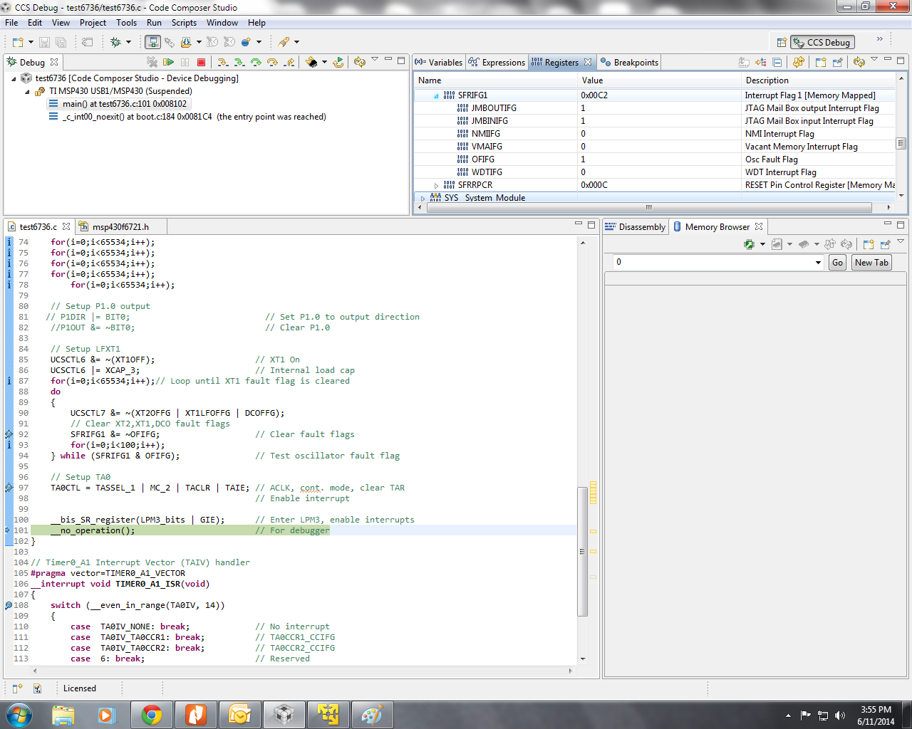
here i attach 2 screen shots .in which you can see that there is DCOFF and OFIFG flag is set still execution beat do- while loop and  reach to (__no_operation()) instruction how this possible????

so please guide how to get crystal working.

  • Your program looks OK.

    There may be some unstable operation of your crystal. Can you check if it is really 32768Hz and soldering looks reliable? DCO/FLL default settings normally works OK without modification with standard crystal. 

    The DCOFF bit set says that DCO is trying hard to deliver default frequency which is around 2MHz on power-up (MCLK = Fdco/2 = 1MHz) and possibly can not do that.

  • yes solder joint is complete and this crystal is 32768 and working fine with another development which has msp430fr5729 controller.

    and this problem is not for only one board i develop another board and it has same issue.

    on board i use single 1.5v cell as source and use switcher ic to boost it to 3.3 v. but i think its not matter with crystal operation...

  • Can you for a test bypass your switcher and power your board from 3V cell instead? Just to make sure that possible bad switcher decoupling does  to affect your crystal circuit operation.

  • oh sorry i forgot that while i debugging i power my board using fet so i think it should be not switcher issue right???  

  • It depends on your schematic, but if the battery is removed the switcher is off. Anyway, check your Vcc voltage.

    Did you try your board without FET connected but powered from the cell? Does it work?

  • yes i tried but not work

  • Hi Karan,

    How do you now that your crystal does not work? MSP430 has fail-safe logic, so if your XT1CLK is in a fault, the device automatically is switched to REFO clock, which is also 32768Hz. Did you try to see what is on XIN, XOUT pins of your device with oscilloscope?

  • i tried to see wave form on xin & xout  pin but on cro there is no wave form so it means internal oscillator not started..... why this happen when i made correct setting?

  • It is probably the crystal you are using is rather pure quality one or you have some errors in PCB layout.

    Do you have external capacitors connected to both sides of your crystal? Do they have correct values? Normally they are too small to place printed values on cases, and if they've been mixed-up, your crystal would never start. You may try to play with values of internal capacitors as well, changing XCAP value to see if it helps.

    On power-up / reset most of the settings for UCS are set to provide most reliable crystal start-up conditions. For example, XT1DRIVE is set to max. Can you have a look in debugger if it is really set to max value?

    Another problem could be your Vcc. Check with oscilloscope whether it fluctuates or stays stable on power-up and later on.

  • i try the following thing 

    1- try various internal capacitor seeting but don't work

    2-external capacitor is there and not shorted on pcb i checked it. try using external capacitor but don't work

    3-XT1DRIVE value remain same i have checked in debugger .

    4-supply is stable i have checked on cro.

    no result

  • > How do you now that your crystal does not work?

    - The reason why I asked is in the first screen capture you've attached the value of XT1LFOFG is 0. Which should mean that nothing wrong with XT1... Can you also attach screen capture where registers UCSCTL0 - UCSCTL3 are also visible? Also instead of going to LPM3 mode can you put there just some dummy infinite loop and set debugger break point inside it?

  • i already tried using while(1) instead of lmp mode but same result.

    and as you see in code i am running timer using aclk. and i frequently check TAR and its not incrementing. not even interrupt is generated.

    and i think fll source is by default aclk and its not available so dco bits roleover to zero and so dcoff flag set 

    and i cant understand XT1LFOFG cleared and not remain set..

  • In order to make sure that your timer code / ISR works OK, can you change your clock configuration so that ACLK is sourced from REFOCLK instead of XT1CLK and see if at least you'll have your timer interrupts working?

  • i already did this and its working on refo clock.problem is with xt1

  • Well, can you replace your crystal with another one? Good old 32768Hz in metal can case. If your MSP part were not F6721, I would suspect XIN, XOUT pins are set as GPIO, but in F6721 these ones are dedicated for crystal use only. The mystery still is why XT1LFOFFG flag stays reset...

  • The spec for F6721 on page 56 says that the fault flag is set if frequency is below 10Hz, might be set if above 10Hz and below 10000Hz and is reset if above 10000Hz. It makes assume that your crystal still provides some sort of oscillation in a range above 10Hz, otherwise the fault flag would be set...

  • I ALREADY CHANGED 2 CRYSTAL BUT PROBLEM IS THERE.

    AND DEVICE IS MSP430F6721 REV A

    AND IF THERE IS OSCILLATION BETWEEN 10HZ ABOVE, WHY ITS NOT SHOWING ON CRO SCREEN AND AT LEAST TIMER RESISTOR SHOULD INCREMENT???

  • Unfortunately you did not provide schematic for your board, but just in case, do you use some back-up supplies in your system apart of main Vcc? If not, did you connect AUXVCC1-2 pins to DVSS and AUXVCC3 to Vcc? If the AUXVCC3 pin on your device in not connected to Vcc, XT1 oscillator is not even powered-up. This may look obvious, but sometimes can be overlooked on hardware design stage...

  • i am not using auxiliary supply apart from vcc.i connect AUXVCC1,AUXVCC2 ,AUXVCC3 to ground. as per note in user guide....

    here i attach screenshot...........

    so where should i connect it to vcc or ground????

  • AUXVCC3 MUST be connected to Vcc!!!  The user's guide just does not have very accurate description of it. 

    It says that "...unused AUXVCC3 must be connected to DVSS." It means that if you do not use RTC, XT1, backup RAM then you must connect AUXVCC3 to DVSS. In your case you do use at least XT1 of the above, so you can not connect it to DVSS, but must connect it to Vcc. In the text above, it is actually mentioned in sub note (1).

  • for precaution purpose i connect one capactior of some micro ferade value .proier i shorted it to provide ground. now i connect capactior there and charging it through internal charger and so now xt1 is working now.

    i want to know how much average current it takes to charge? 

  • pmcore setting lowest,smclk=mclk=1mhz

    so dose it mean while code is being executed it consume 0.32ma and ram consume 0.2ma?????? can you clarify this?

  • You'd better not rely on internal charger. Just connect AUXVCC3 to Vcc externally. You are not going to provide backup battery operation anyway, are you?

    The capacitor value for AUXVCC3 is in spec, and is 0.47uF.

    The charge current for capacitor is only limited by internal charger resistor, its value is configurable from 5 to 20kOhm. Any value will do, it affects charging time only. So the max charge current is limited  in a range of 0.15 to 0.6mA @ Vcc=3V. Of course, when the capacitor is fully charged, the current is near to zero.

  • It means that the current draw is different whether you execute your program from flash or from RAM. Executing program from RAM is much more power efficient and for some cases it is desirable on power-up to copy your program to RAM and execute it from there. It saves power, but complicates programming, because the code must be position-independant. And a RAM space is much smaller than flash, so only small program can fit there.

  • can you clarify for this situation????

    situation 1:

    #include <msp430.h>

    int a;

    void main(void)

    {

    initialization();

    clockconfiguration();

    while(1);

    }

    in this situation current consumption is 250uA. out of this my hardware leakage and other ic consumption is 50uA so i think 200uA is taken by flash because code is executing from there. this consumption is ok.

    situation 2

    #include <msp430.h>

    int a;

    void main(void)

    {

    initialization();

    clockconfiguration();

    while(1)

    {

    a=5+5;

    }

    }

    in this condition consumption is 391uA. so what actually happen when i add only one instruction in while loop that make increment in current consumption??

  • Serge, the datasheet lists this requirement in the description of the auxiliary filter module. It’s easy to find if you know where to look J

    IIRC, it’s also found in the aux module description in the users guide, if you take a look at the drawings (not the text).

     Karan, The difference of your two codes is that in the first code, the program hangs in the while. Which is likely just a one-word branch instruction. This instruction is taken from the flash controller read cache, not from flash itself (after the first read), so in reality, this empty while loop does not run from flash at all.
    The second code is longer, the cache needs to constantly access flash and therefore it draws more. The ‘cache’ is just there because the flash is internally 32 bit while the CPU does 8 or 16 bit reads/writes/fetches – it is not the same as an x86 instruction cache, it has only 32 bit. But in this special case of an empty loop, where there is the same instruction executed over and over again, it really acts as a first level cache and prevents further flash access.
    If you take an MSP of 1x/2x/4x family, you won’t see this as the flash there is internally 16bit.

     Besides this, of course an instruction that does mathematical operations and memory read/write (a is a global var in memory) does use more parts of the CPU than just the empty loop (which only uses instruction fetch and decoding and program counter changes). So a (slightly) higher current is to be expected too.

    If you execute both codes in ram, you’ll likely see the very same current for the first, while the second is still higher, but not as much.

  • Jens-Michael, shouldn't it be more logical if this also is mentioned in UCS section of user's guide? It contains XT1 Oscillator paragraph which lists the conditions for XT1 to be enabled, there are 7 of them. But the major condition - presence of power on AUXVCC3 pin for the devices with aux module - is not there...

  • Agreed, it would be nice. Especially since people tend to only read (if at all) what they think they might need. (I once made this mistake too and it decreased my score at teh final secondary school examinations)

    But if everything that belongs to one module would be explained in the description where it could be useful for, then the users guide would have a million pages.
    (e.g. use of timers in the ADC chapter, clock system in timer/UART/ADC chapters, port pins in every module chapter where there is an external connection used etc.)

    Well, that’s why the forum is there and we can help if someone missed an important detail J

**Attention** This is a public forum