This thread has been locked.

If you have a related question, please click the "Ask a related question" button in the top right corner. The newly created question will be automatically linked to this question.

Watchdog timer

Other Parts Discussed in Thread: MSP430G2553

I came across this sample code(msp430g2553.h) wherein the watchdog resets the controller even as the controller is in sleep mode.

#include <msp430.h>

int main(void)
{
  P1DIR |= 0x01;                            // Set P1.0 to output
  P1OUT ^= 0x01;                            // Toggle P1.0
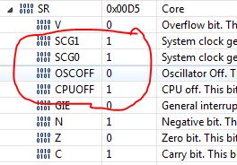
  __bis_SR_register(LPM4_bits);             // Stop all clocks
}

The explanation to this code is as following " The WDT+ will not allow active WDT+ clock to be disabled by software, the LED continues to Flash because the WDT times out normally even though software has attempted to disable WDT+ clock source"

I am confused here as how can SMCLK is still working considering the mode is LPM 4.

Moreover, upon checking the register values, it shows that the MCU is not in LPM 4 rather LPM 3

  • The answer is in the explanation. The WDT prevents it's clock source from being turned off. The example you cite uses SMCLK for the WDT, so when trying to enter LPM, the MCU keeps SMCLK active despite a request otherwise.

  • You are experiencing the irony of "fail-safe".

    When the Watchdog is running and using the clock, this chip will not go into LMP4 even if you tell it to do so. This is what "they" called "fail-safe".

    This is similar to the ABS in a automobile. No mater how hard you step on the break paddle, the break will not entirely stop the wheels from rolling.

    But in your eyes, you probably think not being able to go into LMP4 is a failure. 

  • Thanks for your quick response! 

    However, I still have one question - as per family user guide if SCG0 & SCG1 are high then the SMCLK output should be zero, right? 

    But because of fail-safe feature the SMCLK will be active hence these bits (SCG0 & SCG1) should be low, which is not the case.

  • Vaibhav Ostwal said:
    hence these bits (SCG0 & SCG1) should be low, which is not the case.

    No, because the override logic to the enable of the clock structure happens downstream of the register bits. The WDT doesn't prevent you from writing to those bits, it just prevents those bits from having any effect.

    Similarly there are other peripherals that can hold the clock on by doing the same thing (I think the USCI is one of them), and when they are done with the clock then the CPU register control bits take effect.

  • Vaibhav Ostwal said:
    But because of fail-safe feature the SMCLK will be active hence these bits (SCG0 & SCG1) should be low, which is not the case.


    Besides the fail-safe feature, there’s also the debugger which influences LPM behavior. Check the clock settings in the debugger, as it may prevent the CPU bits from being set.
    As Brian said, the status register bits reflect what you (or the debugger) wrote to them, not what the CPU is actually doing. The bits may be ignored, but they don't change due to internal requirements.
    So the cleared OSCOFF bit has a different reason than ACLK being still required by the WDT.
    (IIRC, if all clocks are off, the debugger cannot access the CPU at all. At least it was this way on older CPU families, giving a ‘cannot access device, CPU halted’ error)

    Sometimes, using a debugger to find a bug will create another bug.

**Attention** This is a public forum