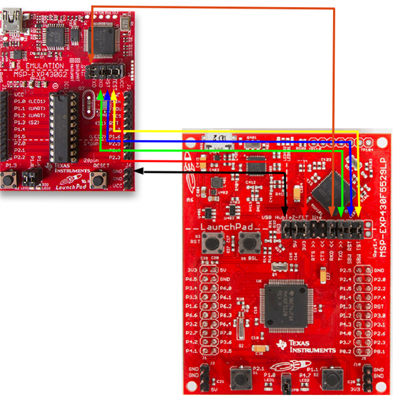
For those that prefer a Linux development environment but want to use the original MSP-EXP430G2 Launchpad and CCS have been frustrated by the lack of Linux support for the eZ430 interface on the MSP-EXP430G2 board, here is one solution.
You can use the eZ-FET lite Emulator on a MSP-EXP430F5529LP Launchpad (in theory a MSP-EXP430FR5969 Launchpad should work also) which is supported on Linux with CCS, connected to the target chip on the MSP-EXP430G2 board.
Tested with CCS 6.0.0.00190 on Linux Mint 15.
Refer to:
MSP-EXP430G2 LaunchPad Evaluation Kit User's Guide (Rev. E)
http://www.ti.com/lit/pdf/slau318
MSP-EXP430F5529LP LaunchPad™ Development Kit User's Guide (Rev. B)
http://www.ti.com/lit/pdf/slau533
According to slau533 MSP-EXP430F5529LP LaunchPad Development Kit User's Guide (Rev. B).pdf, section 2.5 (page 25):
"2.5 Using the eZ-FET lite Emulator With a Different Target
The eZ-FET lite emulator on the F5529 LaunchPad can interface to most MSP430 derivative devices, not
just the on-board F5529 target device.
To do this, disconnect every jumper in the isolation jumper block. This is necessary because the emulator
cannot connect to more than one target at a time over the Spy-Bi-Wire (SBW) connection.
Next, make sure the target board has proper connections for Spy-Bi-Wire. Note that to be compatible with
SBW, the capacitor on RST/SBWTDIO cannot be greater than 2.2 nF. The documentation for designing
MSP430 JTAG interface circuitry is the MSP430 Hardware Tools User's Guide (SLAU278).
Finally, wire together these signals from the emulator's side of the isolation jumper block to the target
hardware:
• 3.3 V
• GND
• 5 V (if needed)
• SBWTDIO
• SBWTCK
• TXD (if the UART backchannel is to be used)
• RXD (if the UART backchannel is to be used)
• CTS (if hardware flow control is to be used)
• RTS (if hardware flow control is to be used)
This wiring can be done either with jumper wires or by designing the board with a connector that plugs into
the isolation jumper block."
So, ignoring 5V, CTS, and RTS, which aren't needed in this case, 6 jumpers is all you need (4 if you don't need a UART connection).
Note: This assumes a Version 1.5 MSP-EXP430G2. For a Version 1.4, you'll need to refer to the schematics in slau318 and make appropriate changes for the TXD and RXD pins.
Disconnect the USB cables from both boards while you connect this up.
Make a note of your current jumper settings on the two boards in case you want to undo this.
Disconnect all jumpers on the isolation jumper blocks on both boards.
And be careful, mis-wiring could short something out.
The jumpers are made from the BOTTOM row of pins (the target chip) on the MSP-EXP430G2 isolation jumper block (J3), to the TOP row of pins (the eZ-FET) on the MSP-EXP430F5529LP isolation jumper block.
The exception to this is the one jumper (orange jumper) on the MSP-EXP430G2 isolation jumper block (see explanation below).
Refer to isolation jumper block (J3) in Figure 9. Schematics, MSP-EXP430G2 Emulator (1 of 2), Revision 1.5 in slau318.
MSP-EXP430G2 .............................................. MSP-EXP430F5529LP
GND <---------------------black--------------------------> GND
VCC <---------------------red----------------------------> 3.3 V
TEST <---------------------yellow-------------------------> TST
RST <---------------------blue---------------------------> RST
If you want a UART connection (this can be confusing on the MSP-EXP430G2 pins, look at the image below):
p1.1 (TOP row pin, labeled RXD) <----------orange------> RXD
P1.2 (BOTTOM row pin, labeled RXD) <----------green-------> TXD
Do not connect the USB cable to the MSP-EXP430G2, power and the FET connection is supplied by the MSP-EXP430F5529LP.
Plug the MSP-EXP430F5529LP into the PCs USB port.
Test downloading and debugging a program to the MSP-EXP430G2 Launchpad.
Note: In the image below, the stock photos of the boards contain the standard jumpers, these must all be removed from the isolation jumper blocks as stated above.
-
Ask a related question
What is a related question?A related question is a question created from another question. When the related question is created, it will be automatically linked to the original question.


