This thread has been locked.

If you have a related question, please click the "Ask a related question" button in the top right corner. The newly created question will be automatically linked to this question.

MSP430 timer block and TAxCTL registers

Hello all.


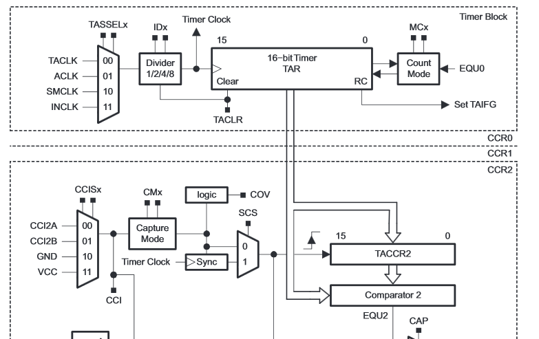
I'm a beginner using the msp430 and I'm trying to get my head around something. I've been reading the msp430 user's guide and looking at timers. Now, to my understanding, the TAR register in the timer block simply counts up/down the value stored in the TACCRx register. The thing that is confusing me, is how can you have and configure multiple clock sources and speeds using the TAxCTL register when you only have on TAR register?

  • Yes, TAR is only counting up or down with the assigned clock (and perhaps a prescaler).

    For multiple counting frequencies or cycle widths at the same time, you’ll need multiple timer instances. That’s why most MSPs have at least two.

    The cycle limit is determined by the CCR0 register, when running in up or up/down mode. In cont mode, the timer simply counts until it overflows and then counts up again from zero.

    If you want to do a PWM, you usually have a fixed PWM frequency, but a variable duty cycle. In this case, CCR0 sets the cycle time and therefore the WPWM frequency, while the other CCRs set the output trigger moment, so the duty cycle of the generated PWM signals.

    Due to the fixed frequency, this won’t help you if you need multiple interrupt frequencies.

    In this case, you can let the timer simply run in cont mode. And when an interrupt is hit by a CCR, you increment the CCR value by the amount of ticks you need to the next interrupt.

    e.g. if the timer counts with 1MHz, you can increment CCR0 by 1000 on each interrupt, giving you the next interrupt 1ms later, while increasing CCR2 by 20000 on each interrupt gives you a 50Hz interrupt interval.
    The only thing is that you must be aware that blocking interrupts for some time (flash write or executing a different ISR that takes some time) might cause the interrupt to e executed when the time for the next one is already due (and your increment of CCRx would lead to a value that has already passed). This needs to be checked in your ISR:
    while ((TA0CCR1-TA0R)>1000) TA0CCR1+=1000;

  • Perfect. Thanks for clearing that up for me. I was getting confused with the diagram. By the looks of the diagram, It looks like there's only one timer block on the msp430, not multiple instances (I guess this is also dependant on the family). If I said anything incorrect, please clarify. I really enjoy working with the msp430

  • There is only one timer block per timer, with multiple CCR blocks. However, there can be multiple instances of a timer in an MSP (IIRC up to 4 times TimerA and one TimerB), with different number of CCR blocks each (2-7). These instances are completely independent, connected to different pins or having different internal links to the ADC or to comparators. And of course with individual clock source settings. These numbers are different for every MSP.

**Attention** This is a public forum