This thread has been locked.

If you have a related question, please click the "Ask a related question" button in the top right corner. The newly created question will be automatically linked to this question.

MSP430G2553 I2C Slave Recieve

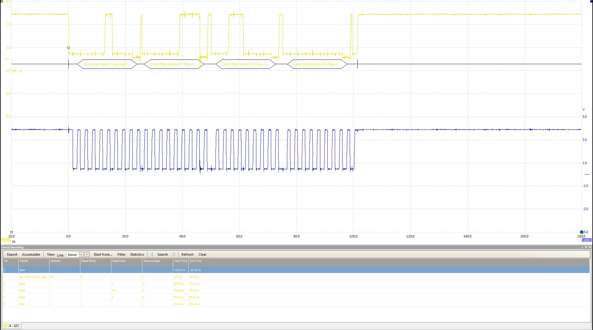
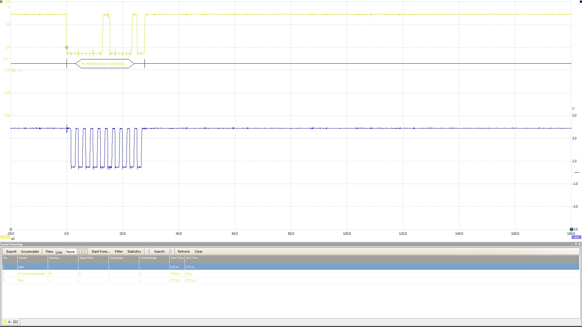
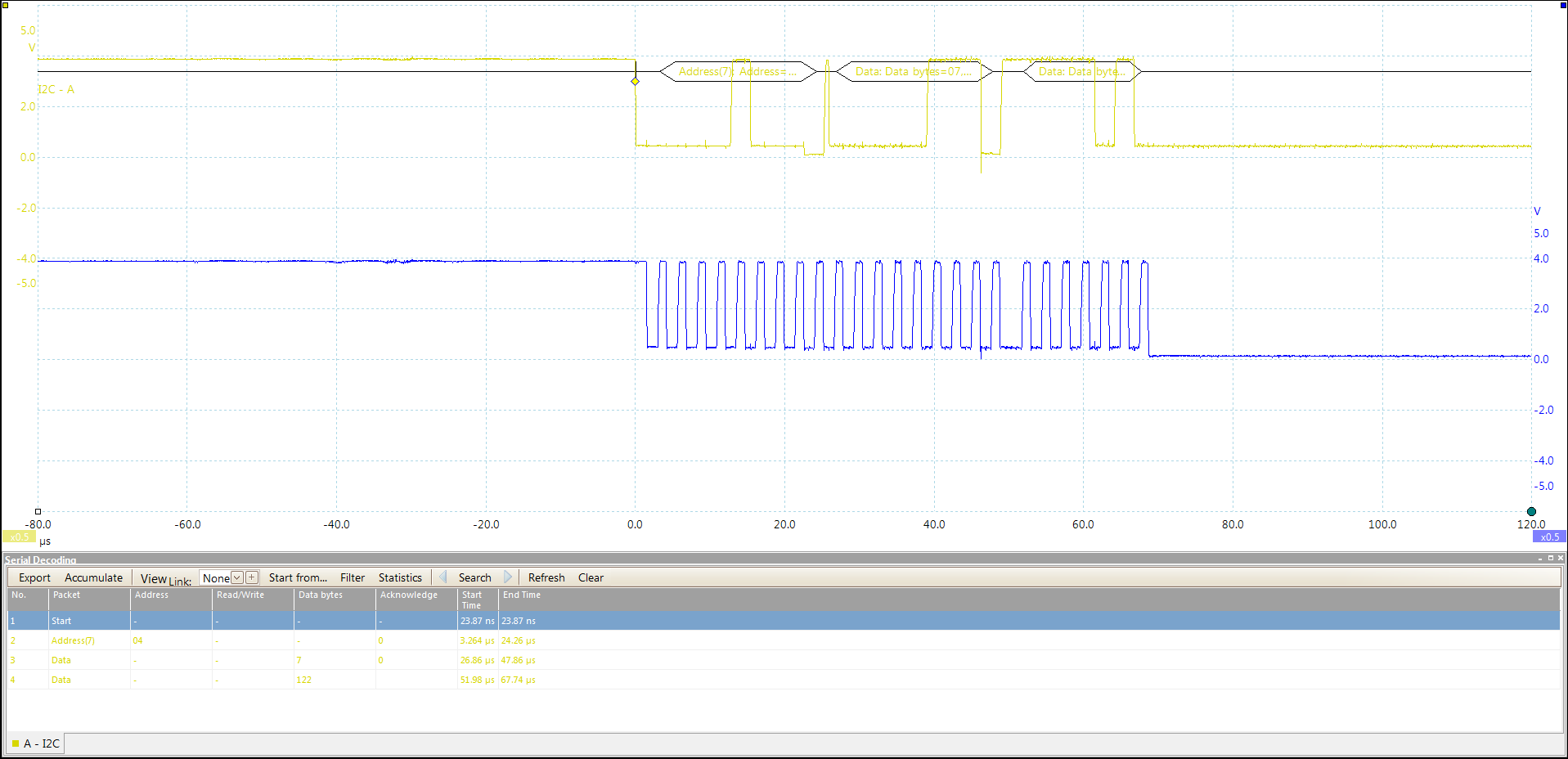
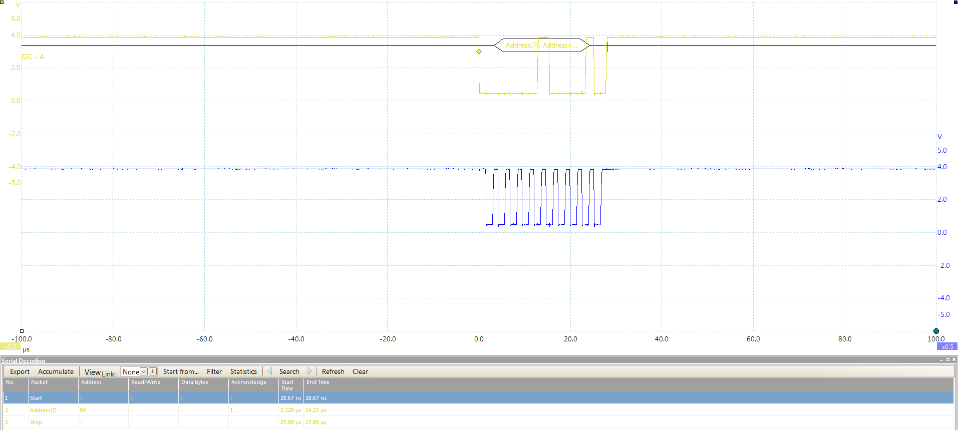
I am having trouble with the slave receive code for the G2553. I am using the Tiva C TM4C1294 as the master transmitter and I have proven to myself that it works because I do not have any problems with the master transmitter code with other slave receivers. However, with the G2553 as the slave receiver, I am only able to receive two random bytes of the message I am sending and then it stops receiving any of that message after receiving it one time. The master is sending the message every 150 ms and I have copied and pasted message I am sending below:

message1[0] = 7;
message1[1] = 244;
message1[2] = 16;
message1[3] = 232;
message1[4] = 48;

I have attached my slave receive code below and some screen shots of what it receives.

8787.I2C_RX.zip

Receives two random bytes of the message sent 


Stops receiving any part of the message

  • It seems you fell into the same trap as many others.
    The users guide states that in I2C mode, one interrupt vector is for RX and TX, while the other is for the status interrupts. It does not tell which is which.
    The datasheet tells you that the TX interrupt is called for RX or TX while the RX interrupt handles the status interrupts.
    The GRACE code enables interrupt for start and stop conditions. For these the RX ISR is called, in which your code handles the RX events.
    The TX ISR is empty and doesn’t handle RX and TX, where it should. OTOH, start and stop interrupts remain unhandled in your code.
    So when the USCI reports a start condition, your code tries to interpret it as RX even and (maybe) fetches a byte. Or it fetches a byte when the stop is reported.

  • So I just have to move the code that's in the RX interrupt into the TX interrupt?

  • For I2C, yes. And inside the ISR, you’ll have to check the IFG bits to determine which one to handle.

  • I updated my ISR routines to reflect what you suggested and I am still having the same problem. I have attached my code below and a snapshot of the I2C bus.

    6175.PWMfromI2C.zip

  • It seems you moved the code to the RX interrupt instead of the TX interrupt.
    Also, normally, you should check what was the interrupt reason. However, in I2C mode there is only either RX or TX, depending on the current transfer, but never both. So as long as you are sure whether you’re receiving or transmitting....

  • I am able to get parts of the message that I am sending now but not all of it. I am sending the following message:

    message1[0] = 7;
    message1[1] = 244;
    message1[2] = 16;
    message1[3] = 232;
    message1[4] = 48;

    Based on the snapshot of the I2C bus, the slave receiver on receives the first byte and part of the second byte. Are you able to see what I am doing wrong?

    4442.PWMfromI2C.zip

  • Looking at your code, I don’t see you handling an I2C transfer. Yes, the USCI is initialized (and starts accepting the incoming transfer), but your code does nothing to actually handle the transfer.

    The RX ISR is empty. However, the USCI is configured to call it in case of a start condition or a stop. So ISR gets called, but doesn’t handle the event. So it gets called again, and again. In the meantime, the first byte is received, but your TX ISR doesn’t read it, as the RX ISR is still be called and called. So the second byte starts receiving, and at the 7th data bit, the USCI hold SCL low to prevent an RXBUF overrun.

    In the RX ISR; you should check for start event, clear the STTIFG bit, and set the number of bytes you want to receive (as the TX ISR counts this down to know when to stop).
    If the RX ISR gets called because of a stop condition before the TX ISR has received all bytes, you know that the master sent less than expected.

  • Thank you for explaining and I added what I think you said but I am still having the same problem. Did I implement what you suggested correctly? If not, do you have a code example of how this is implemented?

    6747.I2C.zip

  • Well, that's not exactly what I meant.
    When you get the UCSTTIFG interrupt, this means that there already was a start condition, with your slave address attached. You don’t send one yourself. But you prepare for the data reception.

    Same for UCSTPIFG. It means there was a stop. You’ll have to somehow tell main that data reception is complete, whether the expected data count was reached or not. Maybe by waking main from LPM and setting a global flag. Something like that.
    In any case, you’ll need to clear these IFG bits (not just cheking them), or else the ISR will be called again and again.

  • Thank you for your help with setting up I2C. I am now trying to send data over the I2C bus to the MSP430 from a Tiva C series board in order to change the frequency, duty cycle, channel, and clock divide of two different Timer modules. Below, I have attached the protocol for how the data is organized and parsed when sending the data. 

    As shown above, if the channel bit is cleared then the PWM signal from pin P1.2 will be changed and if the channel bit is set then the PWM signal from pin P2.2 will be changed. Furthermore, the periodHigh bytes and period bytes are sent as clock ticks. I have copied and pasted a sample message below and explained what is being sent.

    message1[0] = 0x0C;  

    // Clock divide = ID_3 -> 4 MHz / 8 = 500 kHz,

    // Channel = 0: -> P1.2 PWM

    message1[1] = 0xFA;
    message1[2] = 0x00;

    // periodHigh = 250 clock ticks -> 50% Duty Cycle b/c it's 50% of the period's clock ticks

    message1[3] = 0xF4;
    message1[4] = 0x01;

    // period = 500 clock ticks -> 500 kHz / 500 clock ticks = 1 kHz

    So since I have explained how I have set everything up, I will now explain what problem I am having. The PWMs work by them selves but as soon as I start sending data over the I2C bus, the PWM modules die and no longer generate a PWM on either one of the pins. Do you know why this is? I have attached my code below.

    5050.PWMfromI2C.zip

**Attention** This is a public forum