This thread has been locked.

If you have a related question, please click the "Ask a related question" button in the top right corner. The newly created question will be automatically linked to this question.

INTERNAL REFRENCE ON MSP430F247TPMR

Other Parts Discussed in Thread: MSP430F247

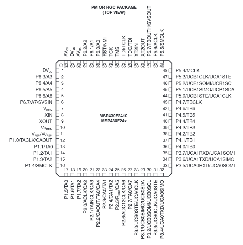
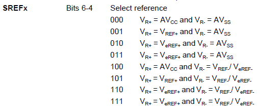
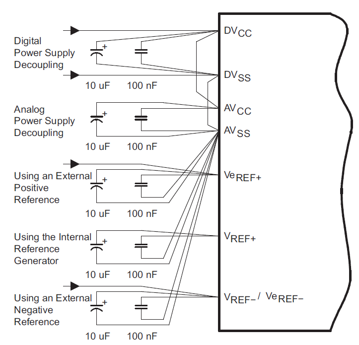
Customer is planning on using the internal refernce on the MSP430F247TPMR.  They wnat to confirm the connections are correct.  The schemaitc for the internal refernce pins is attached.  Please check that they have connected them correctly.


1373.MSP430 Internal Reference.docx

Thanks for your help.

Regards,

John WIemeyer


  • If you want to use the internal reference voltage (1.5V or 2.5V, depending on the REF2_5V-bit) with respect to AVss ground, which is the commonly used configuration while using the internal reference, then your schematic is maybe not completely wrong, but unusual. I have never tried enabling the internal reference and feeding it into Veref+, because this not necessary - you can tie several things together inside the MSP by setting some bits.

    Have a look at the pin-configuration of the MSP430F247:

    You just need the pin Vref+, which is for the internal positive reference voltage - this is the built in 1.5V / 2.5V reference which has to be buffered outside the MSP.

    In your picture...

    ...you are using the pins Vref+, Veref+ and Vref-/Veref-. But Veref+ is only for an external reference voltage which you don't want to use - so this one is "wrong". As mentioned before...using the internal reference, making it an external one by feeding it back into Veref+ is really unusual, although it should work, too - why not? Vref-/Veref- is a common pin for the negative terminal. This is not absolutely wrong, but not necessary, too, because the MSP can tie this pin internally to ground by setting the appropriate configuration bits. Anyway - you can use this pin if you want to.

    This is the configuration for the reference used during your sampling:

    So use Vref+ only and set SREF to 001 which ties Vref- internally to GND, or tie Vref- to GND externally as if you have done in your schematic and use SREF 101. Or try your special construction by setting SREF to 110 - I would not go this way... Vref-/Veref- is used to feed in a voltage that is different from GND. This could be useful in an application where a voltage divider with two series resistors is used. One of them (precise fixed value) generates the reference voltage and the other one is an NTC/PTC for example, both sourced by an constant current source. This application would be ratiometric and is often used for temperature measurement.

    And one more thing: You are using 100n in parallel to 2.2u - the advice of the datasheet is to use 100n in parallel to 10u:

    Regards, Dennis

  • In addition to the (otherwise correct) information from Dennis, I want to add some recommendations:

    It is recommended to connect DVcc and AVcc with a 10 to 100 Ohm resistor (10, if you use the DAC and activate the reference output and need some output current, 100 if you are only sampling with the ADC). This makes the caps on AVcc not only work for decoupling but also as a low-pass filter for removing any digital ripple form DVcc.
    It is also recommended to not connect DVss and AVss directly. Instead, route them separately to the supply GND point. This prevents any GND currents (worst case: ripples) on the digital GND to raise the GND reference for the analog pin.

    Of course all external analog circuitry should, if possible and if not sinking significant currents, connected to this analog GND too.

**Attention** This is a public forum