Hi All,
For one of our products we want to use the MSP430F5359 as MCU. After looking at the datasheet we saw that the MCU has two PU pins. The data sheet says that these pins are high current:
The Port U Pins (PU.0 and PU.1) function as general-purpose high-current I/O pins. These pins can only be
configured together as either both inputs or both outputs. Port U is supplied by the LDOO rail. If the 3.3-V LDO is
not being used in the system (disabled), the LDOO pin can be supplied externally.
Does this mean that the current is 3.3v only, there is no way there could be 1.8v on these pins when setting them "high"?
When not using usb, these pins function as normal I/O pins but with a higher voltage?
Is it possible to set these pins around 1.8 volt when the pins are high? The reason that i post this question is that we want to use one of the PU pins as a output pin. On the other end want to connect a Input pin of the PAN1326 Bluetooth chip. We want to connect the nshutdown pin to PU1.
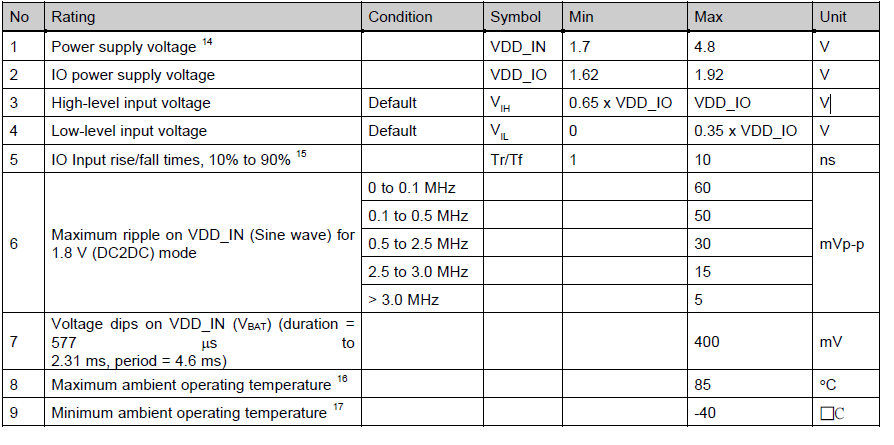
But in the PAN1326 data sheet in the recommended table we see a lower recommeded I/O voltage (max 1.92).
Does anybody have a sugesstion? Is using a normal I/o pin a good suggestion?
Below is the table of the PAN1326 datasheet: