This thread has been locked.

If you have a related question, please click the "Ask a related question" button in the top right corner. The newly created question will be automatically linked to this question.

MSP430G2553 PWM Control via I2C Communication


Thank you for your help with setting up I2C. I am now trying to send data over the I2C bus to the MSP430 from a Tiva C series board in order to change the frequency, duty cycle, channel, and clock divide of two different Timer modules. Below, I have attached the protocol for how the data is organized and parsed when sending the data. 

As shown above, if the channel bit is cleared then the PWM signal from pin P1.2 will be changed and if the channel bit is set then the PWM signal from pin P2.2 will be changed. Furthermore, the periodHigh bytes and period bytes are sent as clock ticks. I have copied and pasted a sample message below and explained what is being sent.
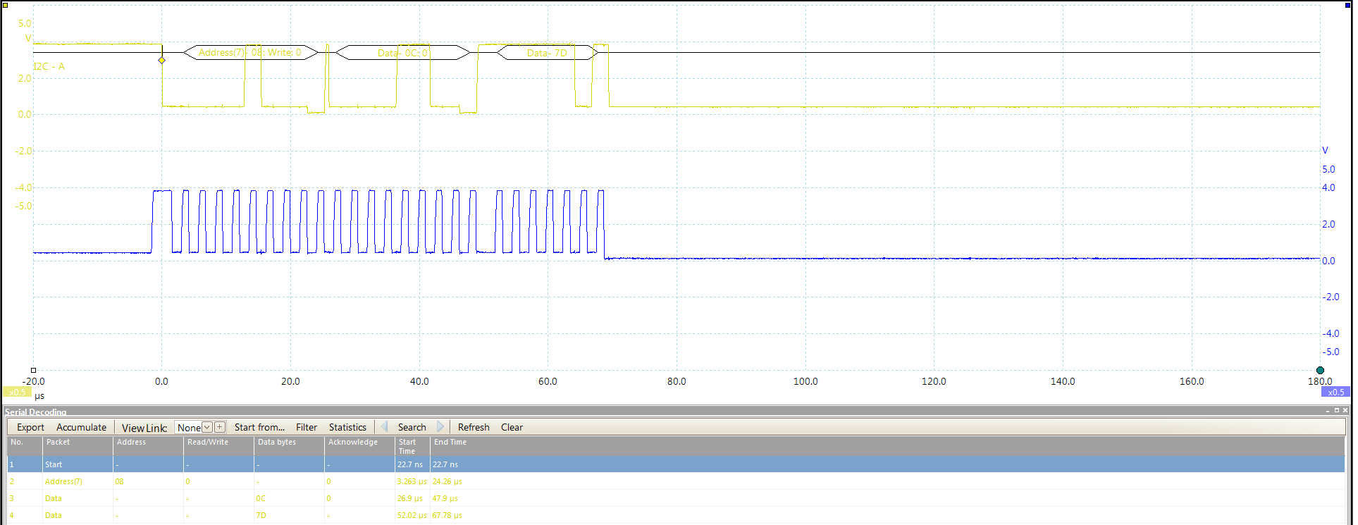
message1[0] = 0x0C;  

// Clock divide = ID_3 -> 4 MHz / 8 = 500 kHz,

// Channel = 0: -> P1.2 PWM

message1[1] = 0xFA;
message1[2] = 0x00;

// periodHigh = 250 clock ticks -> 50% Duty Cycle b/c it's 50% of the period's clock ticks

message1[3] = 0xF4;
message1[4] = 0x01;

// period = 500 clock ticks -> 500 kHz / 500 clock ticks = 1 kHz

So since I have explained how I have set everything up, I will now explain what problem I am having. The PWMs work by them selves but as soon as I start sending data over the I2C bus, the PWM modules die and no longer generate a PWM on either one of the pins. Do you know why this is? I have attached my code below.

5050.PWMfromI2C.zip

  • Hi Andrew!

    First thing I have to say is that I'm not familiar with this GRACE stuff and I don't know which code snippets are generated by GRACE automatically and which is your own. To be honest - I don't like GRACE very much because this automated code generation may be easy, but in most cases you don't really learn how to set up your micro properly. But this is my opinion and I don't mind if people want to do so.

    Some things in your code make me wonder a little bit. First is your RX/TX interrupts. Why do you use both? You're just receiving data, aren't you? Furthermore you're reading your received byte in the TX-ISR. This will never pop up I think. This could be the reason why your PWM stops after any transmission. Look at your RX-ISR and what you are doing in it - you are setting the "new" control bit. This RX-ISR will be called after you have received a byte, but you never read this byte from the RX-buffer because this is done in your TX-ISR. Your PRxData is propably all zero after startup and since copying the received byte from your RX-buffer to this array is in the TX-ISR PRxData remains zero. This zero is then copied to your timer-control in the timer ISR which stops it.

    Next thing in your RX-ISR is that you do not wait for all bytes to be received, but you are changing divide, periodHigh and period in every RX interrupt even if byte 1, 2, 3 and 4 haven't been received yet. This will cause your timer to do things you do not want until all bytes came in. So work with a byte counter and set a flag after all data has been received and then change your settings.

    Your timer ISRs look strange, too. For example TIMER0_A0_VECTOR has no TA0IV_TACCR1 - this belongs to TIMER0_A1_VECTOR. Same for the other timer. Maybe you read this:

    http://e2e.ti.com/support/microcontrollers/msp430/f/166/p/381874/1346638.aspx#1346638

    And why do you trigger on TAIFG? Why not using the hardware PWM with OUTMOD_7?

    Dennis

  • To help you a little bit with your code:

    // Your variables
    
    unsigned char change_timer_flag = 0;
    
    void main( void )
    {
      // Configure your clock
      // Configure your ports and their functions
      // Configure your USCI
      ...
      // Setting up your timer
      TA0CCR0    =  1000;                // Period
      TA0CCR1    =  500;                 // Duty-cycle
      TA0CCTL1   =  OUTMOD_7;            // Reset/set
      TA0CTL     =  ( TASSEL_2 | MC_1 ); // SMCLK, up-mode
    
      TA1CCR0    =  1000;                // Period
      TA1CCR1    =  500;                 // Duty-cycle
      TA1CCTL1   =  OUTMOD_7;            // Reset/set
      TA1CTL     =  ( TASSEL_2 | MC_1 ); // SMCLK, up-mode
    
      // Enable global interrupts
    
      while( 1 )
      {
        // Do something else
    
        if( change_timer_flag )
        {
          switch( RxBuffer[0] & 0x01 )
          {
            case 0:
            {
              // Set your new settings for PWM 1
              break;
            }
            case 1:
            {
              // Set your new settings for PWM 2
              break;
            }
          }
    
          change_timer_flag = 0;
        }
      }
    }
    
    #pragma vector = USCIAB0RX_VECTOR
    __interrupt void USCI0RX_ISR_HOOK( void )
    {
      RxBuffer[RXByteCtr++] = UCB0RXBUF;
      
      if( RXByteCtr >= 5 )
      {
        RXByteCtr = 0;
        change_timer_flag = 1;
      }
    }

    If you want to power down your MCU you can do the code that is executed after the flag is checked in your RX-ISR, too, of course. But wait for all bytes to be reiceived.

  • Dennis,

    Thank you for your help and I understand that you prefer not to use GRACE but I set-up the I2C communication using the suggestion given in the I2C section of the GRACE configuration interface. I have taken a screen shot of this and copied and pasted it below.

    Thanks again,

    Andrew

  • Dennis,

    I made the changes that you suggested and now I seem to have issues with the I2C now even though I did not change anything that has to do with that. I have attached my code below and a screen shot of my I2C bus.

    1538.PWMfromI2C.zip

**Attention** This is a public forum